
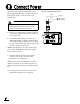
Installation Instructions


5
Once you have identified a suitable antenna
mounting site, according to the guidelines
provided on page 4, follow these steps to prepare
the mounting site for installation.
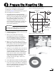
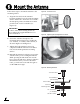
a. Unfold the antenna mounting template
(supplied in the Customer Welcome Kit) and
place it onto the mounting surface. Make sure
the “FWD” (forward) arrow points toward
the bow and is parallel to the vessel’s
centerline (see Figure 4). You don’t need to
mount the antenna exactly on the centerline (the
closer, the better), but the antenna’s forward
arrow must be parallel to it.
b. Using the template, mark the locations for the
four mounting holes.
c. Drill a 5/16" (8 mm) hole at the four
mounting hole locations you marked in
Step b (see Figure 5). Later, you will insert
four 1/4"-20 bolts through these holes to
secure the antenna to the mounting surface.
d. Mark a location for the cable access hole,
either in the center of the antenna mounting
hole pattern or in an area aft of the antenna.
Later, you will route the antenna cable
through this hole and into the vessel.
e. Using a hole saw, drill the cable access hole in
the location you marked in Step d. Be sure to
size the hole appropriately to maintain a
cable bend radius of at least 3" (75 mm). If the
hole location is in the center of the antenna
mounting hole pattern, the diameter of the
cable access hole must not exceed 3.5"
(88 mm). Smooth the edges of the hole to
protect the cable.
f. Clean and dry the antenna mounting surface.
g. Peel off the paper backing from the supplied
foam seal to expose the adhesive. Then press
the foam seal down firmly onto the mounting
surface, centered between the antenna
mounting holes (see Figure 6).
X
15.5"
(39.4 cm)
2.8"
(7.1 cm)
5.6"
(14.2 cm)
4.6" (11.7 cm)
9.2"
(23.4 cm)
4 x 0.31"
( 0.8 cm)
Mounting Holes
Cable Access Hole
(Suggested)
Antenna Base
Figure 4: Antenna Mounting Holes Layout
Be sure the mounting surface is flat and level.
Use a separate mounting plate, if necessary.
IMPORTANT!
Figure 5: Drilling Antenna Mounting Holes
Center
Between
Mounting
Holes
Figure 6: Foam Seal
Prepare the Mounting Site
3