
Installation Instructions

15
Follow these steps to set the antenna’s LNB to the
skew angle you noted in the previous step.
a. Turn off and unplug your satellite TV
receiver.
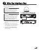
b. Press the power switch on the front of the
interface box to disconnect power from the
TracVision system. Make sure the VOLTAGE
status light goes out.
c. Remove the three #10-32 screws securing the
radome to the antenna. Carefully remove the
radome and set it aside in a safe place.
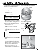
d. Locate the LNB on the back of the antenna’s
reflector (see Figure 26).
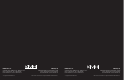
e. Loosen the two wing screws securing the
LNB to the choke feed (see Figure 27).
f. Adjust the LNB, clockwise or counter-
clockwise, until the skew arrow on the LNB
points to the correct skew angle on the choke
feed.
g. Tighten the wing screws to secure the LNB in
place.
h. Reinstall the antenna’s radome. The radome’s
“TracVision” labels should face fore and aft
(see Figure 28). While pressing the radome
down onto the base, secure the radome to the
base using the three #10-32 screws you
removed earlier.
i. Install a protective plastic screw cap
(supplied in the kit) over each radome screw.
CAUTION
Disconnect power from the antenna before
you remove the radome. The antenna has
moving parts that can cause injury.
Reflector
LNB
Figure 26: Location of LNB on Back of Antenna Reflector
+
0
–
10
20
30
40
50
60
70
10
20
30
40
50
60
70
5
15
25
35
45
55
65
5
15
25
35
45
55
65
Choke Feed
Skew Arrow
Wing Screw
(1 of 2)
LNB
Figure 27: LNB Skew Angle Adjustment
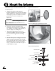
Make sure the LNB is fully inserted into the
choke feed. The shaft of the LNB must be
seated properly against the feed tube to
ensure optimum performance.
IMPORTANT!
Figure 28: Radome Labels Facing Fore and Aft
Set the LNB Skew Angle
13