Installation Guide Linear Configuration TracVision M3/M2 TracVision M3/M2
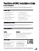
TracVision M3/M2 Installation Guide Linear Configuration These instructions explain how to install the TracVision M3/M2 satellite TV antenna system on a vessel. Complete instructions on how to use the system are provided in the User’s Guide. Installation Steps 1. Inspect Parts and Get Tools...3 8. Connect Power...10 2. Plan the Installation...4 9. Mount the Interface Box...11 3. Prepare the Mounting Site...5 10. Turn On the System...12 4. Wire the Antenna...6 11. Enter Your Latitude & Longitude...
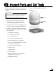
1 Inspect Parts and Get Tools Before you begin, follow these steps to make sure you have everything you need to complete the installation. Figure 1: TracVision M3/M2 System Components Antenna IMPORTANT! Always lift the antenna by the baseplate and never by the radome or any portion of the internal antenna assembly (see Figure 1). Radome a. Unpack the box and ensure it contains everything shown on the Kitpack Contents List. Save the packaging for future use. b.
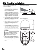
2 Plan the Installation Before you begin, consider the following installation guidelines: • • • Minimize blockage. The antenna requires a clear view of the sky to receive satellite TV (see Figure 2). The fewer obstructions, the better the system will perform. Make sure the mounting surface is wide enough to accommodate the antenna’s base (see Figure 3). Also make sure it is flat, level (within ±2°), strong enough to support the antenna’s weight (18 lbs/8.2 kg), and rigid enough to withstand vibration.
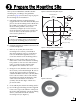
3 Prepare the Mounting Site Once you have identified a suitable antenna mounting site, according to the guidelines provided on page 4, follow these steps to prepare the mounting site for installation. a. Unfold the antenna mounting template (supplied in the Customer Welcome Kit) and place it onto the mounting surface. Make sure the “FWD” (forward) arrow points toward the bow and is parallel to the vessel’s centerline (see Figure 4).
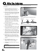
4 Wire the Antenna Follow these steps to connect the antenna cable to the antenna. Figure 7: Removing the Connector Cover a. Using the supplied 3 mm Allen hex key, remove the connector cover from the antenna’s base (see Figure 7). Save the cover and the four M4 cap screws for later use. b. Route the antenna cable belowdecks through the cable access hole. Be sure to keep the end of the cable with the rubber sealing boot at the antenna site. c.
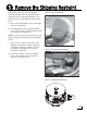
5 Remove the Shipping Restraint Follow these steps to remove the shipping restraint, which prevents the internal antenna assembly from moving during shipment. The antenna will not work with this restraint still in place. Figure 11: Removing the Radome a. Remove the three #10-32 screws securing the radome to the antenna. b. Carefully lift the radome straight up until clear of the antenna assembly and set it aside in a safe place (see Figure 11).
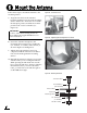
6 Mount the Antenna Follow these steps to mount the antenna to the mounting surface. Figure 14: “Forward” Arrow a. Align the four holes in the antenna’s baseplate with the four holes in the mounting surface. Ensure the “Forward” arrow inside the baseplate points toward the bow and is parallel to the vessel’s centerline (see Figure 14). IMPORTANT! Be sure to insert the mounting bolts from above and use the supplied hardware for a secure installation.
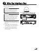
7 Wire the Interface Box Follow these steps to connect the antenna cable and receiver to the interface box. Figure 17: Wiring the Interface Box IMPORTANT! Do not shorten or extend the antenna cable. Since the cable carries data, power, and communications, the integrity of this cable and its connections is very important. Antenna (A) Deck Interface Box IMPORTANT! Be sure to route cables within the vessel appropriately to avoid damage.
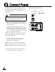
8 Connect Power The interface box requires 10-16 VDC power input supporting 50 watts (4.2 amps @ 12 VDC). Follow these steps to connect power to the interface box. Figure 18: Interface Box Power Wiring Black Ground Red Ferrite Coil CAUTION For your own safety, disconnect vessel power and make sure the circuit is dead before you connect any power wires. a. Before you connect the power wires, turn off vessel power and test the circuit to ensure no power is present. b.
9 Mount the Interface Box Once all cables are connected, follow these steps to install the interface box inside the vessel. Figure 19: Interface Box Mounting a. Attach the two mounting brackets to the sides of the unit using three #2-56 screws. Simply screw these fasteners into the vent slots (see Figure 19). 1⁄4" Fasteners (x4) (not supplied) IMPORTANT! To avoid overheating, do not block the upper vents of the interface box. b.
10 Turn On the System Follow these steps to turn on the system for the first time. Figure 20: Interface Box Power Switch and Status Lights a. Ensure the antenna has a clear, unobstructed view of the sky. b. Apply power to the TV and the receiver. c. Press the power switch on the front of the interface box to apply power to the TracVision system (see Figure 20). d. Wait one minute for system startup. e. Verify that the VOLTAGE and RECEIVER status lights on the interface box are lit green.
11 Enter Your Latitude & Longitude Follow these steps and refer to the flowchart in Figure 23 to enter your vessel’s latitude and longitude into the system. The antenna will use this position information to calculate the proper LNB skew setting for your position and speed up satellite acquisition. If you are located in Europe and don’t know your latitude and longitude, you can use the approximate latitude/longitude for your region shown in Figure 24.
12 Select Satellites Follow these steps and refer to the flowchart in Figure 25 to set up the antenna for the customer’s desired satellites. You may choose up to four satellites from the following list: • Arabsat, 26° E • Nilesat, 7° W • Astra 1, 19.2° E • Optus D1, 160° E • Astra 2N, 28.2° E • Optus C1, 156° E • Astra 2S, 28.2° E • Pas 9, 58° W • Eutelsat W3A, 7° E • Sirius, 5° E • Hispasat, 30° E • Thor, 0.
13 Set the LNB Skew Angle Follow these steps to set the antenna’s LNB to the skew angle you noted in the previous step. Figure 26: Location of LNB on Back of Antenna Reflector Reflector a. Turn off and unplug your satellite TV receiver. b. Press the power switch on the front of the interface box to disconnect power from the TracVision system. Make sure the VOLTAGE status light goes out. LNB CAUTION Disconnect power from the antenna before you remove the radome.
14 Educate the Customer Before you leave the vessel, test the system to verify proper operation. Then give the Customer Welcome Kit and all manuals to the customer and explain how to use the system. Also be sure the customer understands the following: • Figure 29: Blockage Example Keep the radome installed on the antenna at all times. The radome protects the antenna’s moving parts from wind, rain, and debris.
KVH Industries, Inc. 50 Enterprise Center Middletown, RI 02842-5279 U.S.A. Phone: +1 401 847-3327 Fax: +1 401 849-0045 E-mail: info@kvh.com Internet: www.kvh.com © Copyright 2008 KVH Industries Inc. KVH Europe A/S Kokkedal Industripark 2B 2980 Kokkedal Denmark Phone: +45 45 160 180 Fax: +45 45 160 181 E-mail: info@kvh.dk Internet: www.kvh.com KVH, TracVision, and TracPhone are registered trademarks of KVH Industries Inc. KVH Industries, Inc. 50 Enterprise Center Middletown, RI 02842-5279 U.S.A.