Satellite Television A Guide to TracVision L3/S3 • • Installation Instructions User’s Guide Technical Manual ® • KVH TracVision L3/S3 owner’s manual
Congratulations! You have selected one of the most advanced land-mobile satellite tracking systems available today. KVH® Industries’ TracVision® L3/S3 is designed for use with European and North American DVB-compatible satellite services as well as DIRECTV®. This manual provides detailed instructions on the proper installation, use, and maintenance of your TracVision L3/S3 system.
TracVision®, KVH®, and TracNet™ are trademarks of KVH Industries, Inc. DVB® (Digital Video Broadcasting) is a registered trademark of the DVB Project. DIRECTV® is an official trademark of DIRECTV, Inc., a unit of GM Hughes Electronics. DISH Network™ is an official trademark of EchoStar Communications Corporation. ExpressVu is a property of Bell ExpressVu, a wholly owned subsidiary of Bell Satellite Services. DirecPC® is a registered trademark of Hughes Network Systems, a unit of GM Hughes Electronics.
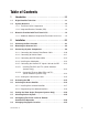
Table of Contents 1 Introduction . . . . . . . . . . . . . . . . . . . . . . . . . . . . . . .1-1 1.1 Digital Satellite Television . . . . . . . . . . . . . . . . . . . . . . . . . . . . . .1-1 1.2 System Overview . . . . . . . . . . . . . . . . . . . . . . . . . . . . . . . . . . . .1-2 1.2.1 TracVision L3/S3 Components . . . . . . . . . . . . . . . . . . . . . .1-3 1.2.2 Integrated Receiver Decoder (IRD) . . . . . . . . . . . . . . . . . . .1-3 1.3 Materials Provided with TracVision L3/S3 . . . . .
3 Using Your TracVision L3/S3 . . . . . . . . . . . . . . . . . . . . .3-1 3.1 Turning On the System . . . . . . . . . . . . . . . . . . . . . . . . . . . . . . . .3-1 3.2 Changing Channels and Switching Between Satellites . . . . . . .3-2 3.2.1 Using the IRD Remote Control to Switch Between Satellites . . . . . . . . . . . . . . . . . . . . . . . . . . . . . . .3-2 3.2.2 Using the TV/SAT Switch to Switch Between Satellites . . . . . . . . . . . . . . . . . . . . . . . . . . . . . . .3-3 3.2.
5.3 Replaceable Parts . . . . . . . . . . . . . . . . . . . . . . . . . . . . . . . . . . . .5-2 5.4 Field Replaceable Unit Procedures . . . . . . . . . . . . . . . . . . . . . .5-3 5.4.1 PCB Removal and Replacement . . . . . . . . . . . . . . . . . . . . .5-5 5.4.2 RF Detector/DVB Decoder . . . . . . . . . . . . . . . . . . . . . . . . .5-6 5.4.3 Antenna Gyro Assembly (TracVision L3 only) . . . . . . . . . . .5-7 5.4.4 Antenna LNB Replacement . . . . . . . . . . . . . . . . . . . . . . . .5-8 5.
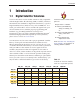
Introduction 1 Introduction 1.1 Digital Satellite Television Your new TracVision L3/S3 satellite antenna is fully compatible with the Digital Video Broadcasting (DVB®) satellites, which use the international standard for digital TV transmission, as well as Digital Satellite Service (DSS) services, such as DIRECTV®. As a result, you will be able to receive and decode signals from your chosen satellite services with the proper programming and hardware (e.g., the IRD [satellite TV receiver]).
A Guide to TracVision L3/S3 Table 1-2 Available European Satellite Pairs (European LNB Required) Astra 1 Astra 2N Astra 2S ✓ ✓ Astra 1 Hispasat Hotbird Sirius ✓ ✓ Astra 2N ✓ ✓ Astra 2S ✓ ✓ Thor Hispasat Hotbird ✓ Sirius ✓ ✓ ✓ ✓ ✓ ✓ ✓ Thor 1.2 If you are a DISH 500 customer, you can order the optional TV/SAT Switch – free of charge. Simply fill out the order form located at the back of this manual and fax it to KVH at +1 401 845-8190.
Introduction In-motion Tracking (TracVision L3 only) The TracVision L3 employs a state-of-the-art actively stabilized antenna system. Once the satellite is acquired, the antenna gyro continuously measures your vehicle’s motion and position, and transmits commands to the antenna motors to keep the antenna pointed at the satellite at all times. 1.2.1 TracVision L3/S3 Components The antenna unit includes the antenna positioning mechanism, signal front end, power supply, and control elements.
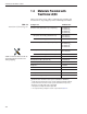
A Guide to TracVision L3/S3 1.3 Materials Provided with TracVision L3/S3 Table 1-3 lists the units, cables, and materials packed in the TracVision L3/S3 package by name and KVH part number. Table 1-3 TracVision L3/S3 Packing List Component KVH Part No.
Introduction 1.3.1 Additional Materials Required for TracVision L3/S3 Use To make full use of your new TracVision L3/S3 and receive satellite TV on the road, you will need to provide/purchase the following: • Television • Appropriate IRD for your selected satellite TV service 54-0157 Rev. G In North America, you can purchase and/or activate an IRD directly from KVH. Call KVH at 1-888-584-4163 for details.
Installation 2 Installation TracVision L3/S3 is designed for simple installation and setup. Just follow these easy steps: Step Refer to Section... 1. Choose the hardware locations 2.1 2. Mount the antenna unit 2.2 3. Connect system components 2.3 4. Activate the IRD 2.4 5. Select active satellite 2.5 6. Set the skew angle (Europe only) 2.6 7. Check out system 2.7 8. Configure for remote dish use 2.
A Guide to TracVision L3/S3 Kitpack Contents Table 2-2 lists the materials provided in the kitpack. Table 2-2 Kitpack Contents Part KVH Part No. Tie-wraps 5 22-0013 Clamshell ventilator 1 19-0230 #6 x 3⁄4" thread-forming screws 3 14-0298-12 ⁄4"-20 x 5⁄8" hex screws 4 14-0250-0010 1 ⁄4" flat washers 4 14-0251 Switchplate bulb assembly (spare) 1 19-0193 ⁄8" hole plugs 2 19-0282-06 1 3 2-2 Qty.
Installation 2.1 Choosing the Best Location • Since the TracVision antenna requires a clear view of the southern sky to receive satellite signals, the ideal antenna site has an unobstructed view of the horizon/satellite all around. • Keep the antenna clear of any obstructions on the roof (e.g., air conditioners). The antenna requires a 15º to 75º look angle to receive satellite signals.
A Guide to TracVision L3/S3 2.2 Always lift the antenna unit by the gray baseplate, never by the radome or any portion of the antenna assembly! Figure 2-3 Proper Orientation of the Antenna Unit Mounting the Antenna Unit 1. Make sure that you have chosen a suitable mounting location based upon the guidelines in Section 2.1, “Choosing the Best Location.” 2. Remove the antenna unit from its shipping carton. 3.
Installation 7. Seal the two baseplate holes shown in Figure 2-4 with the plugs provided in the kitpack. Figure 2-4 Antenna Baseplate (Bottom View) Baseplate Holes 8. Apply construction adhesive to the bottom of the antenna’s four mounting plates. If using a liquid construction adhesive, apply beads to the mounting plates in a zig-zag pattern. 9. Reposition the antenna, lining up the mounting plate holes with the holes in the roof.
A Guide to TracVision L3/S3 11a.(Alternate Drain Hole Locations) If the antenna unit is installed with the connectors facing the front of the vehicle, drill out 3⁄16" (5 mm)-drain holes in the rear-facing side of the baseplate as illustrated in Figure 2-6. The existing factory-drilled drain holes shown in Figure 2-5 must then be plugged with silicone rubber sealant.
Installation 13. Remove the nuts and washers securing the shipping restraints to the baseplate. The positions of all three shipping restraints are pictured in Figure 2-8. Figure 2-8 TracVision L3/S3 Shipping Restraints (Top View, Installed for Shipping) Rotating Plate Shipping Restraint Forward Shipping Restraint for LNB Bracket Rotating Plate Shipping Restraint 14.
A Guide to TracVision L3/S3 Figure 2-11 TracVision L3/S3 Shipping Restraints (Storage Position) Rotating Plate Shipping Restraint Forward Shipping Restraint Rotating Plate Shipping Restraint 15. Place the radome onto the baseplate (labels facing the sides of the vehicle) and secure in place using the 8 pan head screws and flat washers removed in Step 10. 16. Drill the cable access hole (marked in Step 4) in the vehicle’s roof.
Installation 2.3 Connecting System Components The following sections provide instructions for properly wiring the antenna unit to the components inside the vehicle. Locating the Switchplate A switchplate has been provided to serve as the hub of the TracVision L3/S3 wiring (with the exception of the RF cable, which will be connected to the IRD). This switchplate includes an ON/OFF switch and a DB9 maintenance port for easy access to the antenna unit’s software and diagnostics.
A Guide to TracVision L3/S3 2.3.1 Connecting the Antenna Data/Power Cable 1. Connect one end of the antenna data/power cable to the antenna’s data/power connector and lock in place (see Figure 2-13). Figure 2-13 Antenna Data/Power Connector Data/Power 2. Route the other end of the data/power cable down through the cable access hole in the vehicle’s roof and out through the switchplate panel cutout. 3.
Installation 2.3.2 Connecting to Vehicle Power Recommended Power Wiring Short circuits may result in severe electrical shock or burns. Remove the appropriate vehicle fuse and test the circuit to ensure that no power is present before connecting the power cable. The switchplate requires an 11-16 VDC power input. A quicktripping circuit breaker or fuse should be installed between the switchplate and vehicle power. Circuit overload protection should be rated for 5 amperes.
A Guide to TracVision L3/S3 2.3.3 Connecting the IRD Ground Wire A grounding wire (Cable #32-0583-50) has been provided to connect your IRD to a suitable ground and protect the system. Attach the grounding wire to any suitable screw on the rear panel of the IRD with a good contact with the IRD chassis. The other end should be connected to a suitable ground, ideally the ground connector on the switchplate (see Figure 2-15). 2.3.
Installation 2.3.5 Connecting the Antenna RF Signal Cable to the IRD 1. Route an RF cable up through the roof’s cable access hole. 2. Connect the RF cable to the antenna’s RF1 connector (see Figure 2-17). Once the cable is securely connected, loosen the sealing nut at the base of the RF1 connector and tighten it onto the end of the RF cable. When shipped from the factory, the antenna’s RF connectors are protected with caps.
A Guide to TracVision L3/S3 2.3.5.2 Connecting Three or More IRDs and TVs (North American Systems Only) To install three or more IRD/TV pairs, an active multiswitch (Channel Master model 6214IFD or equivalent) must be placed between the antenna unit and the IRDs. Figure 2-18 illustrates typical wiring arrangements for multiple IRDs. If more than four IRDs are required, contact KVH for additional wiring instructions. Mount the multiswitch unit in accordance with the manufacturer’s instruction sheet.
Installation 2.3.6 Sealing the Cable Access Hole Once the RF and data/power cables are connected to the antenna, you need to seal and cover the cable access hole to protect against leakage. 1. Completely seal the cable access hole with silicone sealant or RTV. 2. Install the clamshell ventilator, supplied in the kitpack, over the cable access hole using the three supplied #6 screws (see Figure 2-19).
A Guide to TracVision L3/S3 2.5 Selecting the Active Satellite As noted previously, TracVision L3/S3 can track a variety of DVB-compatible and DSS (DIRECTV) satellites. The system contains a preprogrammed library of North American and European satellites. It also has two open slots that you may use to program two additional satellites of your choice. Tables 2-3 and 2-4 provide a grid of possible satellite pairs.
Installation The satellites listed in TracVision L3/S3’s satellite library will be sufficient for most users. However, if you wish to install one or two user-defined satellites, proceed to Section 2.5.2, “Programming User-defined Satellites.” After configuring the user-defined satellites, return to the satellite installation process in Section 2.5.1, “Installing Your Selected Satellites.” 2.5.
A Guide to TracVision L3/S3 3. Apply power to the TracVision L3/S3 system and allow the system to complete full initialization. Data should be scrolling on the PC display to identify any system problems detected. If no data is seen, recheck your connections and the terminal software setup.
Installation For example, to assign Astra 2S and Hotbird for your satellite pair, and to track Astra 2S, you would enter the following data: SATINSTALL,ASTRA2S,HOTBIRD @L,A ZAP 2.5.2 Programming User-defined Satellites The TracVision L3/S3 satellite library has two open slots that you may use to program two user-defined satellites in case you want to install/watch a satellite that is not in the KVH predefined list.
A Guide to TracVision L3/S3 Entering User-defined Satellite Data Once the link between the PC and the TracVision L3/S3 is established as described in Section 2.5, “Selecting the Active Satellite,” you need to provide initial longitude data regarding the user-defined satellite.
Installation This information has to be entered for each of the following transponder categories: • vertical high • vertical low • horizontal high • horizontal low right • left or • TracVision L3/S3 requires that the data fields for all transponder categories be provided.
A Guide to TracVision L3/S3 An Example of Configuring a User-defined Satellite (Europe) The following is an example of configuring the fictional YOURSAT 101 as the USER1 configured satellite. Prior to configuring this satellite or any others, be certain to get the most up-to-date information from one of the sources previously discussed. Table 2-7 Sample User-defined Satellite Configuration (Europe) YOURSAT 101 at 7 West, DVB decoder, Linear Polarization LNB Horizontal High Frequency 11.
Installation An Example of Configuring a User-defined Satellite (N. America) The following is an example of configuring the fictional YOURSAT 101 as the USER1 configured satellite. Prior to configuring this satellite or any others, be certain to get the most up-to-date information from one of the sources previously discussed. YOURSAT 101 at 71 West, DVB decoder, Circular Polarization LNB Right Frequency 11.966 GHz Symbol Rate 27500 FEC Code 3/4 Network ID 2048 (dec) = 0x0800 Frequency 11.
A Guide to TracVision L3/S3 2.6 Setting the Skew Angle (European Systems Only) The Antenna LNB skew angle must be adjusted to optimize channel reception. Refer to your satellite service provider for the proper skew angle for the selected satellite service and geographical location. The skew angle for KVH predefined satellites can also be obtained by using a PC connected to the maintenance port. Enter your latitude and longitude using the GPS command (refer to Appendix E.
Installation 2.7 Checking Out the System To complete the TracVision L3/S3 installation, it will be necessary to verify that the system functions properly. Critical to ensuring that the system is configured and operating properly is to check the system startup routine to ensure that the system is operating within normal parameters. To do so, it is necessary to connect a PC to the terminal maintenance port.
A Guide to TracVision L3/S3 2.8 Configuring TracVision L3/S3 for Remote Satellite Dish Operation In some campground locations, dense foliage will block the satellite signal. In these situations, a remote portable antenna may be the only solution to satellite signal reception. The wiring option for the remote dish is very simple and should be installed when the TracVision L3/S3 is installed.
Installation 2.9 Changing Geographic Location If you move from Europe to the U.S., or from the U.S. to Europe, you will need to modify your TracVision L3/S3 system to receive satellite TV signals in the new geographic area. To begin receiving satellite signals in the new area, perform the following steps. Swap LNBs To receive the proper satellite signals in the new geographic location, your TracVision antenna must be equipped with the appropriate LNB for that location. If moving from Europe to the U.S.
Using Your TracVision L3/S3 3 Using Your TracVision L3/S3 For TracVision L3/S3 to receive the satellite signals, the antenna must have a clear line of sight to the satellite. If you only receive intermittent signals or the antenna cannot find the satellite, check around your vehicle for any objects that could be blocking the signal, such as trees, buildings, highway overpasses, etc.
A Guide to TracVision L3/S3 Figure 3-2 Turning on the TracVision L3/S3 Using the Switchplate 3. Turn on the antenna using the switchplate, as pictured in Figure 3-2. 4. (TracVision L3 only) If the vehicle is moving, avoid turning the vehicle for 60 seconds after turning on the antenna to allow the antenna gyro to initialize properly. 3.2 If you are a DISH 500 customer, you can order the optional TV/SAT Switch – free of charge.
Using Your TracVision L3/S3 EchoStar Satellite Subscribers EchoStar subscribers will need to use the optional TV/SAT Switch or a PC to change satellites, as described in the following sections. 3.2.2 Using the TV/SAT Switch to Switch Between Satellites - Optional If you are a DISH 500 customer, or you’re unable to switch between satellites using the IRD remote control, you can use the optional TV/SAT Switch (see Figure 3-3) to easily select between Satellite A and Satellite B.
A Guide to TracVision L3/S3 2. The Sat A and Sat B indicators blink while the system initializes. 3. Either the Sat A or Sat B indicator will turn solid green, denoting which satellite is currently being tracked. Using the TV/SAT Switch The TV/SAT Switch is very easy to use. All operations are controlled through the single Select button. To select the second satellite, perform the following steps: 1. Press the Select button on the TV/SAT Switch. 2.
Using Your TracVision L3/S3 2. Open the terminal emulation software and establish the following settings: • 9600 baud • no parity • 8 data bits • 1 start bit • 1 stop bit • no flow control 3. Once the data connection is made, enter the Satellite Selection command as follows: Command: @L,x ( indicates a carriage return/ENTER key) Where: x = A or B (whichever satellite you want to track) To select Satellite A, you would enter @L,A. To select Satellite B, you would enter @L,B. 4.
A Guide to TracVision L3/S3 Cable Unwrap The antenna unit can rotate a full 720° before coming to the end of its cable. If it does so, the system automatically unwraps the cable by quickly rotating the dish in the opposite direction. During this process, your television transmission will be frozen momentarily while the cable unwraps and the antenna reacquires the satellite.
Using Your TracVision L3/S3 Conical Scan Tracking (TracVision L3 only) The antenna control unit uses conical scanning to maintain peak signal strength to the receiver and to update the satellite’s position. When conical scan tracking is active, the antenna moves continually with a circular motion to sweep across the satellite’s peak signal. The signal strength is then fed back to the control circuits to keep coming back to the direction of the strongest signal.
Troubleshooting 4 Troubleshooting The troubleshooting matrix shown in Table 4-1 identifies some trouble symptoms, their possible causes, and references to troubleshooting solutions. SSI BLE CAU Blo wn SE fuse (AN DS or im Inco OLU rrec pro TIO per t sa N) w telli iring Sat te c ellit ( o S n e si ecti figu gna on 4 ratio Dew l blo .1.1 n ( or r cke S ) e ctio ain d (S n 4. poo ecti Sat 1 l o i ellit ng o .2) n 4. e co n do 1.3) vera m Veh e ge i (Se icle ssu ctio turn e (S n 4. ing Inco e 1.
A Guide to TracVision L3/S3 4.1.1 Blown Fuse or Improper Wiring If the antenna unit is installed but entirely non-responsive, there are three key factors to check as part of the troubleshooting process: 1. Blown Fuse – The antenna unit is equipped with two fuses mounted on its CPU Board. If either of these fuses has blown or been broken, the antenna unit will not operate. Refer to Section 5.4.1, “PCB Removal and Replacement,” for details on the fuse locations and how to access the CPU Board. 2.
Troubleshooting 4.1.4 Dew or Rain Pooling on Dome Dew or rain can occasionally pool on the top of the radome. While this moisture will usually be dispersed when the vehicle is in motion, it can disrupt the signal while the vehicle is at rest. This issue can be minimized with two approaches: 1. Spray the dome with hosed water to remove the dew from the dome surface. 2. Periodically apply liquid dish detergent to the dome surface. Wipe the full-strength detergent on the dome and allow it to dry.
A Guide to TracVision L3/S3 4.1.8 Type of Multiswitch Used (North American Systems Only) Baseline RF levels are included as part of the startup sequence provided in Appendix D. An active multiswitch must always be used to connect the TracVision L3/S3 system to multiple IRDs. Refer to Section 2.3.5, “Connecting the Antenna RF Signal Cable to the IRD,” for directions on proper multiswitch/multiple IRD cabling. 4.1.
Troubleshooting 4.4 Computer Diagnostics TracVision L3/S3 has been designed to provide diagnostic readouts on a personal computer having an RS-232 serial communication port. If you are unable to isolate a system problem with the foregoing troubleshooting tools, set up a laptop to carry out computer diagnostics as described below. System problems will most likely be found somewhere through the diagnostic readouts.
Maintenance 5 Maintenance 5.1 Warranty/Service Information For information on KVH warranty, repair, and liability policies, please refer to the complete warranty statement provided at the conclusion of this manual. If you have any questions, please call your local authorized dealer/installer or distributor, or contact KVH or KVH Europe directly. 5.2 Preventive Maintenance TracVision L3/S3 requires minimal preventive maintenance. The following tasks are sufficient to maintain peak performance.
A Guide to TracVision L3/S3 5.3 The serial number of your TracVision L3/S3 will be required during any troubleshooting or service calls. You will find the serial number at the front of this manual. Replaceable Parts TracVision L3/S3 has been designed with durability and low maintenance in mind. If you experience an operating problem or otherwise require technical assistance, contact your local authorized TracVision L3/S3 dealer/distributor first.
Maintenance 5.4 Field Replaceable Unit Procedures The following subsections provide detailed procedures for repairing or swapping out field replaceable units. The procedures refer to labeled items presented on the following diagrams.
A Guide to TracVision L3/S3 Figure 5-3 Antenna Assembly TracVision L3 only Antenna Gyro Cable Wing Screw and Washer Locking Nuts and Washers Reflector Bracket LNB Clamp LNB Antenna Gyro Antenna Gyro Gasket Figure 5-4 Close-up of RF Detector and PCB Rotating Plate RF Board PCB Cable Clamp Screw Antenna Gyro Cable (TracVision L3 only) 5-4 Cable Clamp
Maintenance 5.4.1 PCB Removal and Replacement Estimated Time to Repair: 1⁄2 hour The microprocessor PCB assembly is protected by a cover fastened to the rotating plate – Fig. 5-1. The cover must be removed to gain access to the main power fuses and the PCB assembly. 1. Using needle-nose pliers, remove the E-ring from one end of the connecting rod – Fig. 5-2. 2. Remove the connecting rod by sliding it off the bracket.
A Guide to TracVision L3/S3 Figure 5-6 PCB and RF Detector Board Connector Locations RF Connector to IRD RF Board RF Connector to LNB J1 J3 Fuses Limit Switches Power/Data Gyro (TracVision L3 only) J5 J11 J4 PCB J9 J2 J1 RF Board Elevation Motor Azimuth Motor 7. The PCB is mounted to the rotating plate with 9 pan head screws. Remove the screws and PCB. 8. Reverse this process to install the replacement PCB. Reinstall all cable connectors removed in Step 6.
Maintenance 5. Remove the 4 standoffs – Fig. 5-1. Remove the RF Detector PCB from the rotating plate. 6. Installation of the replacement RF Detector is the reverse of this procedure. Be sure that the RF cables are restored to their original positions. Be sure that the center conductor pin is centered in the connector before tightening the collar. 5.4.
A Guide to TracVision L3/S3 Antenna Gyro Calibration 1. Connect a PC to the communications port as described in Section 4.4, “Computer Diagnostics.” 2. Type HALT ( indicates a carriage return/ ENTER key) while the system is performing the limit switch initialization routine. The system will complete the initialization function by finding the azimuth and elevation switch limits and then go to the home position. 3. Type DEBUGON to enter Debug Mode. 4. Type =CALGYRO.
Maintenance 5.5 Preparation for Shipment If it is necessary to repack the antenna unit for shipment, the shipping restraints removed during installation must be replaced. Follow these steps to reinstall the restraints. 1. Remove the radome. 2. Rotate the antenna unit so that the LNB is facing away from the baseplate connectors. 3.
System Specifications Appendix A System Specifications Physical Characteristics Power 11-16 volts DC @ 2.5 amps nominal, 3.5 amps peak Dimensions/Weight 32" (81 cm) wide x 14.8" (38 cm) high, 33 lbs (15 kg) LNB European system: Single output N.
Comprehensive System Wiring Diagram Appendix B Comprehensive System Wiring Diagram The wiring diagram is presented on the following page. 54-0157 Rev.
54-0157 Rev. G .16" (4 mm) 2.36" (60 mm) 3.19" (81 mm) Panel Cutout 3.82" (97 mm) .32" (8 mm) (2.5 mm) dia 2.
Startup Data Sequence Appendix D Startup Data Sequence The data on the following pages presents standard startup data sequences registered by the TracVision L3/S3. The sequence can be recorded using the data port and a PC. D.1 TracVision L3 Sequence ?PGM KVH TracVision L3 Rev X - Version X.
A Guide to TracVision L3/S3 +POS: 300.8 25.9 162 RF: S,B,V,U,V Satellite Found: AZ = 231.1, EL = 25.9, RF = 1793 +POS: 230.4 25.9 1963 *** Entering Tracking *** RF: S,B,H,U,V +POS: 231.5 26.2 1334 +POS: 231.3 25.8 2023 +POS: 230.6 24.4 2741 RF: Freeze DAC = -00652 +POS: 230.1 23.9 2829 *** Network ID Check ***---------------------Comparing the tracked satellite’s network ID to the +POS: 230.0 23.
Startup Data Sequence *** Initializing Antenna *** GPS: UTC: 083000.00, Lat: 4131.00N, Long: 7115.00W GPS: DSS_119 AZ = 238.9, EL = 22.1 GPS: DSS_101 AZ = 220.9, EL = 33.4 Limit Switch Test Limit Switch Status: PASS----------------------PASS is expected *** Limit Switch Search *** Searching for DSS_101, Threshold = 1000 Satellite Found: AZ = 177.1, EL = 34.0, RF = 1968 RF: Freeze DAC = +01256 +POS: 170.6 34.0 1971 RF: S,A,V,U,V RF: AGAIN #1 *** Initializing Finetune *** +POS: 177.7 34.
Maintenance Port Parser Commands Appendix E Maintenance Port Parser Commands TracVision L3/S3 system parser commands are parsed when the system receives an ASCII carriage return (Hex 0D). An ASCII line feed (Hex 0A) is permitted but is ignored in any transmitted command. All system responses are terminated with an ASCII carriage return followed by a line feed and ending with either an acknowledge character (ASCII > (Hex 3E)) or a not-acknowledge character (ASCII ? (Hex 3F)).
A Guide to TracVision L3/S3 Calibrate Gyro (TracVision L3 only) Function: performs azimuth and elevation calibration Command: CALGYRO Argument: none Response: echoes command and calibrates gyro Find Skew Angle for Currently Selected Satellite Function: calculates necessary LNB skew based on latitude, longitude, and selected satellite Command: SKEWANGLE* Argument: none Response: displays skew angle * Before this command can function properly, you must perform the GPS Position command detaile
Maintenance Port Parser Commands Elevation Angle Function: commands a manual elevation angle that the mechanism moves to Command: EL,xxx (range is 100 - 850) Argument: desired elevation angle of the mechanism relative to up, 10.0° - 85.0° Response: echoes the command; mechanism moves at a fixed velocity Azimuth CW Step Function: commands a 0.1 deg CW manual step in azimuth angle Command: 6 Argument: none Response: echoes the command Azimuth CCW Step Function: commands a 0.
A Guide to TracVision L3/S3 E.3 Operational Commands To execute the following commands, first put the antenna unit in idle mode by typing HALT and pressing “ENTER.” After the system comes to a halt, type DEBUGON and press “ENTER” to enter programming mode.
Maintenance Port Parser Commands Analog Signal Strength Report Function: reports signal strength from RF detector circuit in A/D counts (000-FFF Hex) Command: SIGLEVEL Argument: none Response: Signal Strength = xxxx E.
A Guide to TracVision L3/S3 Report RF Tracking Parameters Function: reports all RF tracking parameters for primary & secondary satellites* Command: @SATCONFIG Response: F,x,fffff,S,C,ID,P,B,D Where: x = Satellite (a = Primary, b = Secondary) fffff = Frequency in MHz (00000 and 10700 to 12700) S = Symbol rate in Mbit/Sec (1000 to 29999) C = FEC code rate (valid rates = 12, 23, 34, 56, 67, 78) ID = Satellite Network ID in hexidecimal format (valid range = 0x0000 to 0xffff hex) P = LNB Polarizatio
Maintenance Port Parser Commands ID Match/Decoded Network ID Function: report ID match and decoded network ID Command: @CHECKID Response: Y,0X#### N,0X#### Y,NoID N,NoID Where: Y = yes N = no 0X#### = network ID NoID = satellite unidentified E.6 Installation Commands To execute the following commands, first put the antenna unit in idle mode by typing HALT and pressing “ENTER.” After the system comes to a halt, type DEBUGON and press “ENTER” to enter programming mode.
A Guide to TracVision L3/S3 Report Satellite Names Function: report names for satellites A and B Command: SATINSTALL Response: SATINSTALL,, Report Configured Satellite Names Function: report names for all configured satellites Command: SATLISTA Response: SATLISTA,,...
Maintenance Port Parser Commands E.7 Debug Commands Report Offset Angles Function: reports system offset angles Command: OFFSETS OFFSETS,XXXXX,YYYY Response: Offsets= XXXXX.X XXXXX.
KVH Industries Limited Warranty TracVision L3/S3 Limited Warranty on Hardware KVH Industries, Inc. warrants the KVH product purchased against defects in materials for a period of TWO (2) years and against factory labor costs for a period of ONE (1) year from the date of original retail purchase by the original purchaser.
TVS3_L3_ OM_ Cover_7_03 ® KVH Europe A/S KVH Industries, Inc. 50 Enterprise Center Middletown, RI 02842 U.S.A. Phone: +1 401 847-3327 Fax: +1 401 849-0045 E-mail: info@kvh.com Internet: www.kvh.com KVH®, TracVision®, and TracNet™ are trademarks of KVH Industries, Inc. Ved Klaedebo 12 2970 Hoersholm Denmark Phone: +45 45 160 180 Fax: +45 45 867 077 E-mail: info@kvh.dk Internet: www.kvh.