Satellite Television A Guide to TracVision R5/R4 • • Installation Instructions User’s Guide Technical Manual ® • KVH TracVision R5/R4 owner’s manual
TracVision R4/R5 Owner’s Manual Addendum (ECO #7564) The following information applies to Revision J of the TracVision R4/R5 Owner’s Manual (KVH Part Number 54-0157). 5.3 Replaceable Parts Table 5-1 has been updated to show the new part number for the RF PCB.
Congratulations! You have selected one of the most advanced land-mobile satellite tracking systems available today. KVH® Industries’ TracVision® R5/R4 is designed for use with European and North American DVB®-compatible satellite services, as well as DIRECTV®. This manual provides detailed instructions on the proper installation, use, and maintenance of your TracVision R5/R4 system. Before using this manual, be sure to check for any addenda, which might detail changes to the manual’s information.
TracVision® and KVH® are registered trademarks of KVH Industries, Inc. The unique light-colored dome with dark contrasting base is a registered trademark of KVH Industries, Inc. DVB® (Digital Video Broadcasting) is a registered trademark of the DVB Project. DIRECTV® is an official trademark of DIRECTV, Inc. DISH Network™ is an official trademark of EchoStar Communications Corporation. ExpressVu is a property of Bell ExpressVu, a wholly owned subsidiary of Bell Satellite Services.
Table of Contents 1 Introduction . . . . . . . . . . . . . . . . . . . . . . . . . . . . . . . . .1-1 1.1 Digital Satellite Television . . . . . . . . . . . . . . . . . . . . . . . . . . . . . . .1-1 1.2 System Overview . . . . . . . . . . . . . . . . . . . . . . . . . . . . . . . . . . . . . .1-2 1.2.1 TracVision R5/R4 Components . . . . . . . . . . . . . . . . . . . . . . .1-3 1.2.2 Satellite TV Receiver . . . . . . . . . . . . . . . . . . . . . . . . . . . . . . .1-3 1.
3 Using Your TracVision R5/R4 . . . . . . . . . . . . . . . . . . . . .3-1 3.1 Turning On the System . . . . . . . . . . . . . . . . . . . . . . . . . . . . . . . . .3-1 3.2 Changing Channels and Switching Between Satellites . . . . . . .3-2 3.2.1 Using the TV/SAT Switch to Switch Between Satellites . . . .3-4 3.2.2 DISH 500 Mode . . . . . . . . . . . . . . . . . . . . . . . . . . . . . . . . . . .3-6 3.3 Watching Television . . . . . . . . . . . . . . . . . . . . . . . . . . . . . . . . . . . .
Appendix A System Specifications . . . . . . . . . . . . . . . . . . .A-1 Appendix B Switchplate Template . . . . . . . . . . . . . . . . . . .B-1 54-0157 Rev.
Introduction 1 Introduction 1.1 Digital Satellite Television Your TracVision R5/R4 satellite TV antenna is fully compatible with the Digital Video Broadcasting (DVB) satellites, as well as Digital Satellite Services (DSS), such as DIRECTV. As a result, you will be able to receive and decode signals from your chosen satellite services with the proper programming and hardware (e.g., the satellite TV receiver).
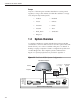
A Guide to TracVision R5/R4 Europe Any two of the European satellites listed below can be paired together, as long as the antenna is within the satellite’s coverage area (European-style LNB required): 1.2 • Arabsat • Hotbird • Astra1 • Nilesat • Astra2N • Sirius • Astra2S • Thor • Eutel_W3A • Turksat1C • Hispasat System Overview A complete satellite TV system includes the TracVision R5/R4 connected to a receiver and a television set.
Introduction In-motion Tracking (TracVision R5 only) The TracVision R5 employs a state-of-the-art actively stabilized antenna system. Once the satellite is acquired, the antenna gyro continuously measures your vehicle’s motion and transmits commands to the antenna motors to keep the antenna pointed at the satellite at all times. 1.2.1 TracVision R5/R4 Components The antenna unit includes the antenna positioning mechanism, signal front end, power supply, and control elements.
A Guide to TracVision R5/R4 1.3 Materials Provided with TracVision R5/R4 Table 1-1 lists the units, cables, and materials packed in the TracVision R5/R4 package by name and KVH part number. Table 1-1 TracVision R5/R4 Packing List Cables for the TracVision R5/R4 are stored beneath the antenna unit during shipping. Component KVH Part No.
Installation 2 Installation Your TracVision R5/R4 is designed for simple installation and setup. Just follow these easy steps: Table 2-1 Installation Process Step Refer to Section... 1. Choose the hardware locations 2.1 2. Mount the antenna unit 2.2 3. Connect system components 2.3 4. Activate the receiver 2.4 5. Select active satellite 2.5 6. Set the skew angle (Europe only) 2.6 7. Check out system 2.7 8. Configure for remote dish use 2.
A Guide to TracVision R5/R4 Kitpack Contents Table 2-2 lists the materials provided in the kitpack. Table 2-2 Kitpack Contents Part KVH Part No. Tie-wraps 5 22-0013 Clamshell ventilator 1 19-0230 #6 x 3⁄4" thread-forming screws 3 14-0298-12 ⁄4"-20 x 5⁄8" hex screws 4 14-0250-10 ⁄4" flat washers 4 14-0251 ⁄8" hole plugs 2 19-0282-06 1 1 3 2-2 Qty.
Installation 2.1 Choosing the Best Location • Since the TracVision antenna requires a clear view of the southern sky to receive satellite signals, the ideal antenna site has an unobstructed view of the horizon/satellite all around. • Keep the antenna clear of any obstructions on the roof (e.g., air conditioners). The antenna requires a 15º to 75º look angle to receive satellite signals (see Figure 2-1).
A Guide to TracVision R5/R4 2.2 Always lift the antenna unit by the gray baseplate, never by the radome or any portion of the antenna assembly! Mounting the Antenna Unit 1. Make sure that you have chosen a suitable mounting location based upon the guidelines in Section 2.1, “Choosing the Best Location” on page 2-3. 2. Remove the antenna unit from its shipping carton. 3.
Installation 7. Seal the two baseplate holes with the plugs provided in the kitpack (see Figure 2-4). Figure 2-4 Antenna Baseplate (Bottom View) Baseplate Holes 8. Apply construction adhesive to the bottom of the antenna’s four mounting plates. If using a liquid construction adhesive, apply beads to the mounting plates in a zig-zag pattern. 9. Reposition the antenna, lining up the mounting plate holes with the holes in the roof.
A Guide to TracVision R5/R4 11. (Standard Installation) When the antenna unit is installed with the connectors facing the rear of the vehicle, the drain holes are located as shown in Figure 2-5.
Installation 12. Cut the tie-wraps holding the antenna unit to the forward shipping restraint (see Figure 2-7). Figure 2-7 Forward Shipping Restraint 2 tie-wraps used to secure LNB arm Shipping Restraint Nuts and Washers Shipping Restraint 13. Remove the nuts and washers securing the shipping restraints to the baseplate (see Figure 2-8).
A Guide to TracVision R5/R4 2.3 Connecting System Components The following sections provide instructions for properly wiring the antenna unit to the components inside the vehicle. Be sure to consider the 28' length of the power and data cables when choosing a location for the switchplate. If you require longer cabling, an additional power supply MUST be used. Failure to install an additional power supply can result in serious damage to the antenna unit.
Installation 2.3.1 Connecting the Antenna Data/Power Cable 1. Connect one end of the antenna data/power cable to the antenna’s data/power connector and lock in place (see Figure 2-10). Figure 2-10 Antenna Data/Power Connector Data/Power 2. Route the other end of the data/power cable down through the cable access hole in the vehicle’s roof and out through the switchplate panel cutout. 3. Connect the data/power cable to the switchplate’s data/power connector and lock in place (see Figure 2-11).
A Guide to TracVision R5/R4 2.3.2 Connecting to Vehicle Power Recommended Power Wiring Short circuits may result in severe electrical shock or burns. Remove the appropriate vehicle fuse and test the circuit to ensure that no power is present before connecting the power cable. The switchplate requires an 11-16 VDC power input. A quicktripping circuit breaker or fuse should be installed between the switchplate and vehicle power. Circuit overload protection should be rated for 5 amps.
Installation 2.3.3 Connecting the Receiver Ground Wire A grounding wire (Cable #32-0583-50) has been provided to connect your receiver to a suitable ground and protect the system. Attach the grounding wire to any suitable screw on the rear panel of the receiver with a good contact with the receiver chassis. The other end should be connected to a suitable ground. 2.3.4 Installing the Switchplate After completing the switchplate wiring process, you must install the switchplate itself.
A Guide to TracVision R5/R4 4. Snap the front cover into place to cover the screws and support frame. 5. Reinstall the vehicle fuse removed in Step 1 of Section 2.3.2, “Connecting to Vehicle Power” on page 2-10. 2.3.5 Connecting the Antenna RF Signal Cable to the Receiver When shipped from the factory, the antenna’s RF connectors are protected with caps. Leave the cap installed on the RF2 connector unless you are going to connect a second RF cable to the TracVision R5/R4. 1.
Installation 2.3.5.2 Connecting Three or More Receivers (North American Systems) To install three or more receivers and TVs, an active multiswitch (Channel Master #6214IFD or equivalent) must be placed between the antenna unit and the receivers. Figure 2-15 illustrates typical wiring arrangements for multiple receivers. If more than four receivers are required, contact KVH for additional wiring instructions. Mount the multiswitch unit in accordance with the manufacturer’s instruction sheet.
A Guide to TracVision R5/R4 4. Terminate all unused output connectors with 75 ohm DC blocks (Channel Master #7184, Radio Shack #15-1259 or equivalent). 2.3.6 Sealing the Cable Access Hole Once the RF and data/power cables are connected to the antenna, you need to seal and cover the cable access hole to protect against leakage. 1. Completely seal the cable access hole with silicone sealant or RTV. Ensure the clamshell mounting screws do not puncture the cables inside the vehicle. 2.
Installation 2.5 Selecting the Active Satellite As noted previously, TracVision R5/R4 can track a variety of DVB-compatible and DSS (DIRECTV) satellites. The system contains a preprogrammed library of North American and European satellites. The satellites listed in the TracVision R5/R4 satellite library will be sufficient for most users. However, you can install up to two user-defined satellites. To install a userdefined satellite, proceed to Section 2.5.
A Guide to TracVision R5/R4 2.5.1 Installing Your Selected Satellites When you first connect to the system, it is preprogrammed with one of the following default satellite assignments: To receive DISH 500 service, you will need to install the following two satellites: Echo_119 & Echo_110 • Europe: Astra 1 (Sat. A) and Hotbird (Sat. B) • N. America (US DIRECTV): DSS_101 (Sat. A) and DSS_119 (Sat. B) • N. America (US DISH Network/ExpressVu): Echo_119 (Sat. A) and Expressvu (Sat.
Installation 2. If you are using HyperTerminal, open it and establish the following settings: • Bits per second: 9600 • Data bits: 8 • Parity: None Table 2-3 Satellite Installation Names • Stop bits: 1 Satellite • Flow control: None North American Satellites If you are using the KVH Flash Update Wizard, double-click the “KVH Flash Update Wizard” shortcut on your computer’s desktop to start the wizard.
A Guide to TracVision R5/R4 4. Type ZAP then press Enter to restart the system. Wait for the antenna to initialize (about 1 minute). Be sure the receiver’s satellite configuration matches your chosen TracVision R5/R4 settings. Example: To assign Astra 2S and Hotbird for your satellite pair, (where Astra2S is designated as Satellite A and Hotbird is designated as Satellite B): Type HALT then press Enter. Type SATINSTALL,ASTRA2S,HOTBIRD then press Enter. Type ZAP then press Enter. 2.5.
Installation Entering User-defined Satellite Data Once the link between the PC and the TracVision R5/R4 is established as described in Section 2.5.1, “Installing your Selected Satellites” on page 2-16, follow the steps below to begin entering the data for your user-defined satellite. 1. Type HALT then press Enter. 2. Type the following command (see the Key below) then press Enter. SATCONFIG,USERX,YYY,Z,D,L Key: X = 1 or 2 (This represents the first or second userdefined satellite.
A Guide to TracVision R5/R4 3. Type @DEBUGON then press Enter. 4. Type the following command (see the Key below) then press Enter. @SATCONFIG,X,N,F,S,C,ID,P,B,D Key: @SATCONFIG = directs data to the RF Board X = satellite location A or B N = satellite table # (98 & 99 are slots for userconfigured satellites) F = frequency in MHz (either 00000 or a range from 10700 - 12700) S = the satellite transponder symbol rate in Mbit/second (01000 - 29999) C = the FEC code (e.g.
Installation TracVision R5/R4 requires that the data fields for all transponder categories be filled in.
A Guide to TracVision R5/R4 An Example of Configuring a User-defined Satellite (Europe) The following is an example of configuring the fictional YOURSAT 101 as the USER1 configured satellite. Prior to configuring this satellite or any others, be certain to get the most up-to-date information from one of the sources previously discussed. Table 2-5 Sample User-defined Satellite Configuration (Europe) YOURSAT 101 at 71 West, DVB decoder, Circular Polarization LNB Horizontal High Frequency 11.
Installation An Example of Configuring a User-defined Satellite (N. America) The following is an example of configuring the fictional YOURSAT 101 as the USER1 configured satellite. Prior to configuring this satellite or any others, be certain to get the most up-to-date information from one of the sources previously discussed. Table 2-6 Sample User-defined Satellite Configuration (North America) YOURSAT 101 at 71 West, DVB decoder, Circular Polarization LNB Right Frequency 11.
A Guide to TracVision R5/R4 2.
Installation Finding the Skew Angle for a Predefined Satellite 1. Type HALT then press Enter. 2. Type DEBUGON then press Enter. 3. Type the following command (see the Key below) then press Enter. GPS,XX,D,YYY,E Key: XX = latitude (0 - 90) D = S (South) or N (North) YYY = longitude (0 - 180) E = E (East) or W (West) 4. Type SKEWANGLE then press Enter. The system will respond with the skew angle for whichever satellite is currently selected. Adjusting the LNB Skew Angle 1.
A Guide to TracVision R5/R4 2.7 Testing the System Now all you need to do is turn the system on and ensure everything works properly. Follow the steps below to test the TracVision system. 1. Park the vehicle in a blockage-free area. The antenna requires an unobstructed view of the southern sky to receive satellite signals. 2. Turn on the receiver(s) and TV(s). For instructions on operating the receiver, refer to the receiver’s User’s Manual. 3. Turn on the TracVision antenna. 4.
Installation 2.8 Configuring TracVision R5/R4 for Remote Satellite Dish Operation In some campground locations, dense foliage will block the satellite signal. In these situations, a remote portable antenna may be the only solution to satellite signal reception. The wiring option for the remote dish is very simple and should be installed when the TracVision R5/R4 is installed. A highquality “A/B switch” should be used to change from TracVision R5/R4 dish reception to remote antenna operation.
A Guide to TracVision R5/R4 2.9 Changing Geographic Location If you move from Europe to the U.S., or from the U.S. to Europe, you will need to modify your TracVision R5/R4 system to receive satellite TV signals in the new geographic area. To begin receiving satellite signals in the new area, perform the following steps. Swap LNBs To receive the proper satellite signals in the new geographic location, your TracVision antenna must be equipped with the appropriate LNB for that location.
Using Your TracVision R5/R4 3 Using Your TracVision R5/R4 For TracVision R5/R4 to receive the satellite signals, the antenna must have a clear line of sight to the satellite. If you only receive intermittent signals or the antenna cannot find the satellite, check around your vehicle for any objects that could be blocking the signal, such as trees, buildings, highway overpasses, etc.
A Guide to TracVision R5/R4 3. Turn on the antenna using the switchplate (see Figure 3-2). The satellite configuration on your receiver must match the satellite setting on the TracVision R5/R4 system. Figure 3-2 Turning on the TracVision R5/R4 Satellite A on the TracVision R5/R4 must be the same satellite as Receiver Alternative 1 (or A, based on your receiver) and must be assigned the Receiver DiSEqC 1 setting.
Using Your TracVision R5/R4 European Services When the TracVision R5/R4 system and the receiver have matching configurations, switching from one satellite to the other is as easy as changing the channel using the remote control. TracVision R5/R4 will automatically switch from Satellite A to B and back again as necessary to receive your selected channel. DIRECTV DIRECTV subscribers in certain regions of the United States will require a DSS Plus receiver to receive broadcasts from multiple satellites.
A Guide to TracVision R5/R4 3.2.1 Using the TV/SAT Switch to Switch Between Satellites To order a TV/SAT Switch (KVH Part Number 01-0245), please call +1 401 847-3327. If you’re unable to switch between satellites using the receiver remote control, you can use the optional TV/SAT Switch to easily select between Satellite A and Satellite B (see Figure 3-3). Figure 3-3 TV/SAT Switch LED Indicators Sat A Error Sat B Select Changing Satellites: 1. Push Select button 2.
Using Your TracVision R5/R4 TV/SAT Switch Controls and Indicators The Select button is used for all operator controls. The TV/SAT Switch also has three LED indicators that show its current status. Table 3-1 explains the function of each indicator.
A Guide to TracVision R5/R4 Using the TV/SAT Switch The TV/SAT Switch is very easy to use. All operations are controlled through a single button. To select the second satellite, perform the following steps: 1. Press the Select button on the TV/SAT Switch. 2. The indicator for the current satellite (Sat A or Sat B) extinguishes, while the indicator for the other satellite starts blinking. 3.
Using Your TracVision R5/R4 6. Using the remote control’s arrow buttons, highlight “Check Switch” then press the Select button. 7. Highlight “Test” then press Select. 8. Wait a minimum of 15 minutes for the Check Switch function to complete and for the antenna to restart and configure itself for DISH 500 mode. If the Check Switch function fails (the receiver locks up), disconnect power from the receiver, restart the antenna, then restore power to the receiver and try the Check Switch function again. 9.
A Guide to TracVision R5/R4 3.3 Watching Television TracVision R5 is designed to operate whether your vehicle is in motion or parked. TracVision R4 is designed to operate only while your vehicle is parked. Using Your TracVision R5/R4 When Parked (TracVision R5 only) Don’t forget to turn the system back on before you start driving again. The antenna must be turned on to track the satellite while you are moving. When your vehicle is stopped, it is not necessary for the TracVision R5/R4 to be turned on.
Using Your TracVision R5/R4 KVH recognizes that some customers may not want to take advantage of this convenient feature. In this case, it is possible to disable Sleep Mode using a simple software command as follows: 1. Connect a laptop computer to the system using the maintenance port and open the KVH Flash Update Wizard or HyperTerminal, as described in Section 2.5.1, “Installing Your Selected Satellites” on page 2-16. 2. Turn on the antenna. When the limit switch test is complete: a.
Troubleshooting 4 Troubleshooting The troubleshooting matrix shown in Table 4-1 identifies some trouble symptoms, their possible causes, and references to troubleshooting solutions. ctio X X Inco ffici ent i r in g er w rop Insu Antenna non-functional Imp SYMPTOM PO SSI BLE CAU SE (Se (AN DS OLU TIO n 4. N) Pow 1.1) er ( rrec Sec t sa tion telli Sat 4.1. te c ellit 2) onfi e si g g u nal ratio Dew b n l o (Se or r cke ctio ain d (S n 4. poo e Sat c t 1.
A Guide to TracVision R5/R4 4.1 If you need technical assistance, please contact KVH Technical Support: Phone: 1-401-847-3327 E-mail: techs@kvh.com Internet: www.kvh.com/help Causes and Remedies for Common Operational Issues There are a number of common issues that can affect the signal reception quality or the operation of the TracVision R5/R4. The following sections address these issues and potential solutions. 4.1.
Troubleshooting 4.1.4 Satellite Signal Blocked Satellite signals can be blocked or degraded by trees and branches, buildings, mountains, overpasses, or equipment on the vehicle itself. Refer to Section 2.1, “Choosing the Best Location” on page 2-3 to make certain that the TracVision R5/R4 unit is in the optimal location. Simply moving the vehicle to clear an external obstruction will also restore signal quality. 4.1.5 Dew or Rain Pooling on Dome Dew or rain can occasionally pool on the top of the radome.
A Guide to TracVision R5/R4 4.1.8 Incorrect or Loose RF Connectors As part of preventive maintenance (as described in Section 5, “Maintenance” on page 5-1), KVH recommends checking the antenna unit cable connections. A loose RF connector can reduce signal quality. In addition, if you are unable to switch to the other programmed satellite, make sure that you have connected your RF signal cable to the antenna baseplate connector labeled “RF1” (see Section 2.3.
Troubleshooting 4.3 Antenna Faults Only KVH-authorized service technicians should perform repairs on the TracVision antenna. Unauthorized repairs on the antenna unit may void the warranty. Contact KVH Technical Support for details. 4.4 Computer Diagnostics TracVision R5/R4 has been designed to provide diagnostic readouts on a PC with a RS-232 serial communication port.
A Guide to TracVision R5/R4 2. If you are using HyperTerminal, open it and establish the following settings: • Bits per second: 9600 • Data bits: 8 • Parity: None • Stop bits: 1 • Flow control: None If you are using the KVH Flash Update Wizard, double-click the “KVH Flash Update Wizard” shortcut on your computer’s desktop to start the wizard. You do not need to flash the antenna to view diagnostic readouts; you will simply view the data in the “TracVision Antenna Comms” window. 3.
Maintenance 5 Maintenance 5.1 Warranty/Service Information For information on KVH warranty, repair, and liability policies, please refer to the complete warranty statement provided with your KVH product. If you have any questions, please call your local authorized dealer/installer or distributor, or contact KVH or KVH Europe directly. 5.2 Preventive Maintenance TracVision R5/R4 requires minimal preventive maintenance. The following tasks are sufficient to maintain peak performance.
A Guide to TracVision R5/R4 5.3 The serial number of your TracVision R5/R4 will be required during any troubleshooting or service calls. You will find the serial number at the front of this manual. Replaceable Parts TracVision R5/R4 has been designed with durability and low maintenance in mind. If you experience an operating problem or otherwise require technical assistance, contact your local authorized TracVision R5/R4 dealer/distributor first.
Maintenance 5.4 Reshipping the Antenna If you need to repack the antenna unit for shipment, the shipping restraints removed during installation must be reinstalled. Follow these steps to reinstall the restraints. 1. Remove the radome. 2. Rotate the antenna unit so that the LNB is facing away from the baseplate connectors. 3.
A Guide to TracVision R5/R4 5. Secure the forward restraint and bracket by wrapping two tie-wraps around the bend in the forward restraint and the antenna bracket (at the end of the LNB bracket) as illustrated in Figure 5-2. IMPORTANT! Before returning the antenna, be sure to obtain an RMA number from KVH’s Technical Support Department and write the number on the outside of the box. Shipments received without an RMA number will be returned to you at your expense.
System Specifications Appendix A System Specifications Table A-1 TracVision R5/R4 System Specifications Physical Characteristics Power 11-16 volts DC @ 2.5 amps nominal, 3.5 amps peak Dimensions/Weight 32" (81 cm) wide x 14.8" (38 cm) high, 33 lbs (15 kg) LNB European system: Single output N.
54-0157 Rev. J .16" (4 mm) 2.36" (60 mm) 3.19" (81 mm) Panel Cutout 3.82" (97 mm) .32" (8 mm) (2.5 mm) dia 2.
TVR5/R4OM_Cover11.05 ® KVH Europe A/S KVH Industries, Inc. 50 Enterprise Center Middletown, RI 02842 U.S.A. Phone: +1 401 847-3327 Fax: +1 401 849-0045 E-mail: info@kvh.com Internet: www.kvh.com Kokkedal Industripark 2B 2980 Kokkedal Denmark Phone: +45 45 160 180 Fax: +45 45 160 181 E-mail: info@kvh.dk Internet: www.kvh.com KVH® and TracVision® are registered trademarks of KVH Industries, Inc.