Satellite Television A Guide to TracVision R5/R4 • • Installation Instructions User’s Guide Technical Manual ® • KVH TracVision R5/R4 owner’s manual
Congratulations! You have selected one of the most advanced land-mobile satellite tracking systems available today. KVH® Industries’ TracVision® R5/R4 is designed for use with European and North American DVB-compatible satellite services as well as DIRECTV®. This manual provides detailed instructions on the proper installation, use, and maintenance of your TracVision R5/R4 system. Before using this manual, be sure to check for any addenda, which might detail changes to the manual’s information.
TracVision® and KVH® are registered trademarks of KVH Industries, Inc. DVB® (Digital Video Broadcasting) is a registered trademark of the DVB Project. DIRECTV® is an official trademark of DIRECTV, Inc. DISH Network™ is an official trademark of EchoStar Communications Corporation. ExpressVu is a property of Bell ExpressVu, a wholly owned subsidiary of Bell Satellite Services.
Table of Contents 1 Introduction . . . . . . . . . . . . . . . . . . . . . . . . . . . . . . . . .1-1 1.1 Digital Satellite Television . . . . . . . . . . . . . . . . . . . . . . . . . . . . . . .1-1 1.2 System Overview . . . . . . . . . . . . . . . . . . . . . . . . . . . . . . . . . . . . . .1-2 1.2.1 TracVision R5/R4 Components . . . . . . . . . . . . . . . . . . . . . . .1-3 1.2.2 Satellite TV Receiver . . . . . . . . . . . . . . . . . . . . . . . . . . . . . . .1-3 1.
3 Using Your TracVision R5/R4 . . . . . . . . . . . . . . . . . . . . .3-1 3.1 Turning On the System . . . . . . . . . . . . . . . . . . . . . . . . . . . . . . . . .3-1 3.2 Changing Channels and Switching Between Satellites . . . . . . .3-2 3.2.1 Using the Receiver Remote Control to Switch Between Satellites . . . . . . . . . . . . . . . . . . . . . . . . . . . . . . . . .3-2 3.2.2 Using the TV/SAT Switch to Switch Between Satellites . . . . . . . . . . . . . . . . . . . . . . . . . . . . . . . . .
5.4 Field Replaceable Unit Procedures . . . . . . . . . . . . . . . . . . . . . . . .5-3 5.4.1 PCB Removal and Replacement . . . . . . . . . . . . . . . . . . . . . .5-5 5.4.2 RF Detector/DVB Decoder . . . . . . . . . . . . . . . . . . . . . . . . . .5-6 5.4.3 Antenna Gyro Assembly (TracVision R5 only) . . . . . . . . . . .5-7 5.4.4 Antenna LNB Replacement . . . . . . . . . . . . . . . . . . . . . . . . . .5-8 5.5 Preparation for Shipment . . . . . . . . . . . . . . . . . . . . . . . . . . . . . . . .
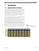
Introduction 1 Introduction 1.1 Digital Satellite Television Your new TracVision R5/R4 satellite antenna is fully compatible with the Digital Video Broadcasting (DVB) satellites, which use the international standard for digital TV transmission, as well as Digital Satellite Service (DSS) services, such as DIRECTV. As a result, you will be able to receive and decode signals from your chosen satellite services with the proper programming and hardware (e.g., the satellite TV receiver).
A Guide to TracVision R5/R4 Table 1-2 Available European Satellite Pairs (European LNB Required) Astra 1 Astra 2N Astra 2S ✓ ✓ Astra 1 Hispasat Hotbird Sirius ✓ ✓ Astra 2N ✓ ✓ Astra 2S ✓ ✓ Thor Hispasat Hotbird ✓ Sirius ✓ ✓ ✓ ✓ ✓ ✓ Thor ✓ 1.2 If you are a DISH 500 customer or you have 3 or more receivers, you can order the optional TV/SAT Switch – free of charge. Simply fill out the order form located at the back of this manual and fax it to KVH at +1 401 845-8190.
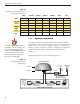
Introduction In-motion Tracking (TracVision R5 only) The TracVision R5 employs a state-of-the-art actively stabilized antenna system. Once the satellite is acquired, the antenna gyro continuously measures your vehicle’s motion and position, and transmits commands to the antenna motors to keep the antenna pointed at the satellite at all times. 1.2.1 TracVision R5/R4 Components The antenna unit includes the antenna positioning mechanism, signal front end, power supply, and control elements.
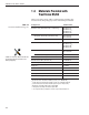
A Guide to TracVision R5/R4 1.3 Materials Provided with TracVision R5/R4 Table 1-3 lists the units, cables, and materials packed in the TracVision R5/R4 package by name and KVH part number. Table 1-3 TracVision R5/R4 Packing List Component KVH Part No.
Introduction 1.3.1 Additional Materials Required for TracVision R5/R4 Use To make full use of your new TracVision R5/R4 and receive satellite TV on the road, you will need to provide/purchase the following: • Television • Appropriate receiver for your selected satellite TV service 54-0157 Rev. H In North America, you can purchase and/or activate a receiver directly from KVH. Call KVH at 1-888-584-4163 for details.
Installation 2 Installation Your TracVision R5/R4 is designed for simple installation and setup. Just follow these easy steps: Step Refer to Section... 1. Choose the hardware locations 2.1 2. Mount the antenna unit 2.2 3. Connect system components 2.3 4. Activate the receiver 2.4 5. Select active satellite 2.5 6. Set the skew angle (Europe only) 2.6 7. Check out system 2.7 8. Configure for remote dish use 2.
A Guide to TracVision R5/R4 Kitpack Contents Table 2-2 lists the materials provided in the kitpack. Table 2-2 Kitpack Contents Part KVH Part No. Tie-wraps 5 22-0013 Clamshell ventilator 1 19-0230 #6 x 3⁄4" thread-forming screws 3 14-0298-12 ⁄4"-20 x 5⁄8" hex screws 4 14-0250-10 ⁄4" flat washers 4 14-0251 ⁄8" hole plugs 2 19-0282-06 1 1 3 2-2 Qty.
Installation 2.1 Choosing the Best Location • Since the TracVision antenna requires a clear view of the southern sky to receive satellite signals, the ideal antenna site has an unobstructed view of the horizon/satellite all around. • Keep the antenna clear of any obstructions on the roof (e.g., air conditioners). The antenna requires a 15º to 75º look angle to receive satellite signals.
A Guide to TracVision R5/R4 2.2 Always lift the antenna unit by the gray baseplate, never by the radome or any portion of the antenna assembly! Figure 2-3 Proper Orientation of the Antenna Unit Mounting the Antenna Unit 1. Make sure that you have chosen a suitable mounting location based upon the guidelines in Section 2.1, “Choosing the Best Location.” 2. Remove the antenna unit from its shipping carton. 3.
Installation 7. Seal the two baseplate holes shown in Figure 2-4 with the plugs provided in the kitpack. Figure 2-4 Antenna Baseplate (Bottom View) Baseplate Holes 8. Apply construction adhesive to the bottom of the Angle of Hole, relative to front antenna’s four mounting plates. If using a liquid construction adhesive, apply beads to the mounting plates in a zig-zag pattern. 9. Reposition the antenna, lining up the mounting plate holes with the holes in the roof.
A Guide to TracVision R5/R4 11a.(Alternate Drain Hole Locations) If the antenna unit is installed with the connectors facing the front of the vehicle, drill out 3⁄16" (5 mm)-drain holes in the rear-facing side of the baseplate as illustrated in Figure 2-6. The existing factory-drilled drain holes shown in Figure 2-5 must then be plugged with silicone rubber sealant.
Installation 13. Remove the nuts and washers securing the shipping restraints to the baseplate. The shipping restraints are pictured in Figure 2-8. Figure 2-8 TracVision R5/R4 Shipping Restraints (Top View) Rotating Plate Shipping Restraint Forward Shipping Restraint for LNB Bracket Rotating Plate Shipping Restraint 14. Remove the shipping restraints and replace the nuts and washers into their original positions. All nuts and washers removed in Step 13 must be reinstalled.
A Guide to TracVision R5/R4 2.3 Connecting System Components The following sections provide instructions for properly wiring the antenna unit to the components inside the vehicle. Locating the Switchplate A switchplate has been provided to serve as the hub of the TracVision R5/R4 wiring (with the exception of the RF cable, which will be connected to the receiver). This switchplate includes an ON/OFF switch and a DB9 maintenance port for easy access to the antenna unit’s software and diagnostics.
Installation 2.3.1 Connecting the Antenna Data/Power Cable 1. Connect one end of the antenna data/power cable to the antenna’s data/power connector and lock in place (see Figure 2-10). Figure 2-10 Antenna Data/Power Connector Data/Power 2. Route the other end of the data/power cable down through the cable access hole in the vehicle’s roof and out through the switchplate panel cutout. 3. Connect the data/power cable to the switchplate’s data/power connector and lock in place (see Figure 2-11).
A Guide to TracVision R5/R4 2.3.2 Connecting to Vehicle Power Recommended Power Wiring Short circuits may result in severe electrical shock or burns. Remove the appropriate vehicle fuse and test the circuit to ensure that no power is present before connecting the power cable. The switchplate requires an 11-16 VDC power input. A quicktripping circuit breaker or fuse should be installed between the switchplate and vehicle power. Circuit overload protection should be rated for 5 amperes.
Installation 2.3.3 Connecting the Receiver Ground Wire A grounding wire (Cable #32-0583-50) has been provided to connect your receiver to a suitable ground and protect the system. Attach the grounding wire to any suitable screw on the rear panel of the receiver with a good contact with the receiver chassis. The other end should be connected to a suitable ground. 2.3.4 Installing the Switchplate After completing the switchplate wiring process, you must install the switchplate itself.
A Guide to TracVision R5/R4 2.3.5 Connecting the Antenna RF Signal Cable to the Receiver When shipped from the factory, the antenna’s RF connectors are protected with caps. Leave the cap installed on the RF2 connector unless you are going to connect a second RF cable to the TracVision R5/R4. 1. Route an RF cable up through the roof’s cable access hole. 2. Connect the RF cable to the antenna’s RF1 connector (see Figure 2-14).
Installation 2.3.5.2 Connecting Three or More Receivers and TVs (North American Systems) To install three or more receiver/TV pairs, an active multiswitch (Channel Master model 6214IFD or equivalent) must be placed between the antenna unit and the receivers. Figure 2-15 illustrates typical wiring arrangements for multiple receivers. If more than four receivers are required, contact KVH for additional wiring instructions. Mount the multiswitch unit in accordance with the manufacturer’s instruction sheet.
A Guide to TracVision R5/R4 4. Terminate all unused output connectors with 75 ohm DC blocks (Channel Master #7184, Radio Shack #15-1259 or equivalent). 2.3.6 Sealing the Cable Access Hole Once the RF and data/power cables are connected to the antenna, you need to seal and cover the cable access hole to protect against leakage. 1. Completely seal the cable access hole with silicone sealant or RTV. 2.
Installation 2.5 Selecting the Active Satellite As noted previously, TracVision R5/R4 can track a variety of DVB-compatible and DSS (DIRECTV) satellites. The system contains a preprogrammed library of North American and European satellites. It also has two open slots that you may use to program two additional satellites of your choice. Tables 2-3 and 2-4 provide a grid of possible satellite pairs. Two of these satellites may be selected to reside in the system’s active memory as Satellites A and B.
A Guide to TracVision R5/R4 The satellites listed in TracVision R5/R4 satellite library will be sufficient for most users. However, if you wish to install one or two user-defined satellites, proceed to Section 2.5.2, “Programming User-defined Satellites.” After configuring the user-defined satellites, return to the satellite installation process in Section 2.5.1, “Installing Your Selected Satellites.” 2.5.
Installation 2. If you are using HyperTerminal, open HyperTerminal and establish the following settings: • Bits per second: 9600 • Data bits: 8 • Parity: None • Stop bits: 1 • Flow control: None If you are using the KVH Flash Update Wizard, double-click the “KVH Flash Update Wizard” shortcut on your computer’s desktop to start the wizard. Then go to the “Select board to flash” screen. You do not need to flash the antenna to configure the satellites; you will simply enter commands in the “Command” box. 3.
A Guide to TracVision R5/R4 3. Type SATINSTALL, , and press Enter. Type None as the name of Satellite B if wish to install only one satellite. Key: = the name of your choice for Satellite A = the name of your choice for Satellite B 4. Type L,X and press Enter to select which of these two satellites the antenna should begin tracking. Key: X = A or B (one of your selectedd satellites defined during the install process) 5.
Installation 2.5.2 Programming User-defined Satellites The TracVision R5/R4 satellite library has two open slots that you may use to program two user-defined satellites in case you want to install/watch a satellite that is not in the KVH predefined satellite library. To configure a user satellite, you will need to obtain the following satellite information from your satellite service provider or from sites on the Internet, such as www.satcodx.
A Guide to TracVision R5/R4 Entering User-defined Satellite Data Once the link between the PC and the TracVision R5/R4 is established as described in Section 2.5, “Selecting the Active Satellite,” follow these steps to begin entering the data for your user-defined satellite. 1. Type HALT and press Enter to place the antenna in Idle Mode. 2. Type following command and press Enter: SATCONFIG,USERX,YYY,Z,D,L Key: X = 1 or 2 (This represents the first or second userdefined satellite.
Installation This information has to be entered for each of the following categories: • vertical high • vertical low • horizontal high • horizontal low right • left or • TracVision R5/R4 requires that the data fields for all transponder categories be provided.
A Guide to TracVision R5/R4 An Example of Configuring a User-defined Satellite (Europe) The following is an example of configuring the fictional YOURSAT 101 as the USER1 configured satellite. Prior to configuring this satellite or any others, be certain to get the most up-to-date information from one of the sources previously discussed. Table 2-7 Sample User-defined Satellite Configuration (Europe) YOURSAT 101 at 71 West, DVB decoder, Circular Polarization LNB Horizontal High Frequency 11.
Installation An Example of Configuring a User-defined Satellite (N. America) The following is an example of configuring the fictional YOURSAT 101 as the USER1 configured satellite. Prior to configuring this satellite or any others, be certain to get the most up-to-date information from one of the sources previously discussed. YOURSAT 101 at 71 West, DVB decoder, Circular Polarization LNB Right Frequency 11.966 GHz Symbol Rate 27500 FEC Code 3/4 Network ID 2048 (dec) = 0x0800 Frequency 11.
A Guide to TracVision R5/R4 2.6 Figure 2-19 Position Grid Table 2-9 Approximate Latitude/Longitude Grid # Setting the Skew Angle (European Systems Only) The Antenna LNB skew angle must be adjusted to optimize channel reception. Refer to your satellite service provider for the proper skew angle for the selected satellite service and geographical location. The skew angle for satellites in the KVH library can also be obtained by entering your latitude and longitude into the antenna.
Installation 4. Type SKEWANGLE and press Enter. The system will respond with the skew angle for whichever satellite is currently selected. Adjusting the LNB Skew Angle 1. Determine the skew angle for the selected satellite and region. 2. Loosen the wing nut on the LNB clamp so that the LNB can be moved. 3. Carefully rotate the LNB so that the scribe mark on the LNB clamp is aligned with the proper angle measurement. Figure 2-18 Skew Adjustment Skew Angles LNB LNB Clamp & Wing Nut Scribe Mark 4.
A Guide to TracVision R5/R4 2.8 If a need arises to paint the radome, ONLY use non-metallic automotive paint to avoid degrading the RF signal strength and the reception quality. Configuring TracVision R5/R4 for Remote Satellite Dish Operation In some campground locations, dense foliage will block the satellite signal. In these situations, a remote portable antenna may be the only solution to satellite signal reception.
Installation 2.9 Changing Geographic Location If you move from Europe to the U.S., or from the U.S. to Europe, you will need to modify your TracVision R5/R4 system to receive satellite TV signals in the new geographic area. To begin receiving satellite signals in the new area, perform the following steps. Swap LNBs To receive the proper satellite signals in the new geographic location, your TracVision antenna must be equipped with the appropriate LNB for that location. If moving from Europe to the U.S.
Using Your TracVision R5/R4 3 Using Your TracVision R5/R4 For TracVision R5/R4 to receive the satellite signals, the antenna must have a clear line of sight to the satellite. If you only receive intermittent signals or the antenna cannot find the satellite, check around your vehicle for any objects that could be blocking the signal, such as trees, buildings, highway overpasses, etc.
A Guide to TracVision R5/R4 Figure 3-2 Turning on the TracVision R5/R4 Using the Switchplate Antenna On/Off Switch 3. Turn on the antenna using the switchplate, as pictured in Figure 3-2. 4. (TracVision R5 only) If the vehicle is moving, avoid turning the vehicle for 60 seconds after turning on the antenna to allow the antenna gyro to initialize properly. 3.2 If you are a DISH 500 customer or you have 3 or more receivers, you can order the optional TV/SAT Switch – free of charge.
Using Your TracVision R5/R4 North America DIRECTV Subscribers DIRECTV subscribers in certain regions of the United States will require a DSS Plus receiver to receive broadcasts from multiple satellites. If connected to the antenna’s RF1 connector, the DSS Plus receiver allows you to switch channels using the remote control. If you are a DIRECTV subscriber, but do not have a DSS Plus receiver, or you are using a multiswitch, use the optional TV/SAT Switch or a PC, as described in the following sections.
A Guide to TracVision R5/R4 Table 3-1 TV/SAT Switch LED Indicators Indicator Status Meaning Sat A Blinking green Wait – Searching for satellite Solid green Tracking Satellite A Error Blinking red System problem – Refer to Section 4, “Troubleshooting,” to find the possible cause Sat B Blinking green Wait – Searching for satellite Solid green Tracking Satellite B Connecting the TV/SAT Switch To use the TV/SAT Switch, you must first connect it to the TracVision system. 1.
Using Your TracVision R5/R4 3.2.3 Using a PC to Switch Between Satellites If you’re unable to switch between satellites using the receiver remote control, you can use a PC connected to the switchplate’s maintenance port to select between Satellite A and Satellite B. The procedure requires a PC with Windows HyperTerminal or download the KVH Flash Update Wizard (available for free at www.kvh.com/wizard). To switch satellites using a PC, perform the following steps: 1.
A Guide to TracVision R5/R4 3. Type @L,X and press Enter once the data connection is made. X = A or B (whichever satellite you want to track) Key: To select Satellite A, type @L,A and press Enter. To select Satellite B, type @L,B and press Enter. 4. The antenna unit shifts to track the second satellite. 3.3 Watching Television TracVision R5 is designed to operate whether your vehicle is in motion or parked. TracVision R4 is designed to operate only while your vehicle is parked.
Using Your TracVision R5/R4 Sleep Mode (TracVision R5 only) When the vehicle has come to a stop and the antenna holds its position for 1 minute, the antenna unit enters Sleep Mode, which turns off the conical scan tracking, reducing any motor noise the antenna may be making. As soon as the vehicle moves, Sleep Mode will automatically be turned off and the system will begin tracking the satellite again.
A Guide to TracVision R5/R4 If the satellite signal is lost while the system is in conical scan track mode, the control software imposes a 45-second time-out delay. If the signal is not regained during that time, the antenna reverts to the set of Search Modes to start looking for the satellite signal. This is an automatic process that does not require user intervention. 3.
Using Your TracVision R5/R4 8. Wait a minimum of 15 minutes for the Check Switch function to complete and for the antenna to restart and configure itself for DISH 500 mode. If the Check Switch function fails (the receiver locks up), disconnect power from the receiver, restart the antenna, then restore power to the receiver and try the Check Switch function again. 9. Run the Check Switch function a second time. This allows the receiver to configure itself for automatic satellite switching. 10.
Troubleshooting 4 Troubleshooting The troubleshooting matrix shown in Table 4-1 identifies some trouble symptoms, their possible causes, and references to troubleshooting solutions. SIB LE CAU Blo wn SE fuse (AN DS or im Inco OLU rrec pro TIO per t sa N) w t ellit iring Sat e co ellit (Se nfig e si ctio gna ura n 4. Dew tion l blo 1.1) (Se or r cke ctio ain d (S n 4. poo ecti Sat 1.2) ling on 4 ellit on d e co .1.3 v o ) era me Veh ge i (Se icle ssu ctio turn e n 4. (Se ing Inco 1.
A Guide to TracVision R5/R4 4.1.1 Blown Fuse or Improper Wiring If the antenna unit is installed but entirely non-responsive, there are three key factors to check as part of the troubleshooting process: 1. Blown Fuse – The antenna unit is equipped with two fuses mounted on its CPU Board. If either of these fuses has blown or been broken, the antenna unit will not operate. Refer to Section 5.4.1, “PCB Removal and Replacement,” for details on the fuse locations and how to access the CPU Board. 2.
Troubleshooting 4.1.4 Dew or Rain Pooling on Dome Dew or rain can occasionally pool on the top of the radome. While this moisture will usually be dispersed when the vehicle is in motion, it can disrupt the signal while the vehicle is at rest. This issue can be minimized with two approaches: 1. Spray the dome with hosed water to remove the dew from the dome surface. 2. Periodically apply liquid dish detergent to the dome surface. Wipe the full-strength detergent on the dome and allow it to dry.
A Guide to TracVision R5/R4 4.1.7 Incorrect or Loose RF Connectors As part of preventive maintenance (described in Section 5, “Maintenance”) KVH recommends checking the antenna unit cable connections. A loose RF connector can reduce signal quality. In addition, if you are unable to switch to the other programmed satellite, make sure that you have connected your RF signal cable to the antenna baseplate connector labeled “RF1” (see Section 2.3.5, “Connecting the Antenna RF Signal Cable to the Receiver”). 4.
Troubleshooting 4.3 Antenna Gyro and LNB Faults Section 5, “Maintenance,” provides detailed instructions for authorized service personnel who may be required to replace TracVision R5/R4 components. The TracVision R4 does not include an antenna gyro. 4.4 Computer Diagnostics TracVision R5/R4 has been designed to provide diagnostic readouts on a PC with a RS-232 serial communication port.
A Guide to TracVision R5/R4 3. Apply power to the TracVision R5/R4 system and allow the system to complete full initialization. Data should be scrolling on the PC display to identify any system problems detected. If no data is seen, recheck your connections and the terminal software setup.
Maintenance 5 Maintenance 5.1 Warranty/Service Information For information on KVH warranty, repair, and liability policies, please refer to the complete warranty statement provided with your KVH product. If you have any questions, please call your local authorized dealer/installer or distributor, or contact KVH or KVH Europe directly. 5.2 Preventive Maintenance TracVision R5/R4 requires minimal preventive maintenance. The following tasks are sufficient to maintain peak performance.
A Guide to TracVision R5/R4 5.3 The serial number of your TracVision R5/R4 will be required during any troubleshooting or service calls. You will find the serial number at the front of this manual. Replaceable Parts TracVision R5/R4 has been designed with durability and low maintenance in mind. If you experience an operating problem or otherwise require technical assistance, contact your local authorized TracVision R5/R4 dealer/distributor first.
Maintenance 5.4 Field Replaceable Unit Procedures The following subsections provide detailed procedures for repairing or swapping out field replaceable units. The procedures refer to labeled items presented on the following diagrams.
A Guide to TracVision R5/R4 Figure 5-3 Antenna Assembly TracVision R5 only Antenna Gyro Cable Wing Screw and Washer Locking Nuts and Washers Reflector Bracket LNB Clamp LNB Antenna Gyro Antenna Gyro Gasket Figure 5-4 Close-up of RF Detector and PCB Rotating Plate RF Board PCB Cable Clamp Screw Antenna Gyro Cable (TracVision R5 only) 5-4 Cable Clamp
Maintenance 5.4.1 PCB Removal and Replacement Estimated Time to Repair: 1⁄2 hour The microprocessor PCB assembly is protected by a cover fastened to the rotating plate – Fig. 5-1. The cover must be removed to gain access to the main power fuses and the PCB assembly. 1. Using needle-nose pliers, remove the E-ring from one end of the connecting rod – Fig. 5-2. 2. Remove the connecting rod by sliding it off the bracket.
A Guide to TracVision R5/R4 Figure 5-6 PCB and RF Detector Board Connector Locations RF Connector to IRD RF Board RF Connector to LNB J1 J3 Fuses Limit Switches Power/Data Gyro (TracVision R5 only) J5 J11 J4 PCB J9 J2 J1 RF Board Elevation Motor Azimuth Motor 7. The PCB is mounted to the rotating plate with 9 pan head screws. Remove the screws and PCB. 8. Reverse this process to install the replacement PCB. Reinstall all cable connectors removed in Step 6.
Maintenance 5. Remove the 4 standoffs – Fig. 5-1. Remove the RF Detector PCB from the rotating plate. 6. Installation of the replacement RF Detector is the reverse of this procedure. Be sure that the RF cables are restored to their original positions. Be sure that the center conductor pin is centered in the connector before tightening the collar. 5.4.
A Guide to TracVision R5/R4 Antenna Gyro Calibration 1. Connect a PC to the communications port as described in Section 4.4, “Computer Diagnostics.” 2. Type HALT and press Enter while the system is performing the limit switch initialization routine. The system will complete the initialization function by finding the azimuth and elevation switch limits and then go to the home position. 3. Type DEBUGON and press Enter to enter Debug Mode. 4. Type =CALGYRO and press Enter.
Maintenance 5.5 Preparation for Shipment If it is necessary to repack the antenna unit for shipment, the shipping restraints removed during installation must be replaced. Follow these steps to reinstall the restraints. 1. Remove the radome. 2. Rotate the antenna unit so that the LNB is facing away from the baseplate connectors. 3.
System Specifications Appendix A System Specifications Physical Characteristics Power 11-16 volts DC @ 2.5 amps nominal, 3.5 amps peak Dimensions/Weight 32" (81 cm) wide x 14.8" (38 cm) high, 33 lbs (15 kg) LNB European system: Single output N.
54-0157 Rev. H .16" (4 mm) 2.36" (60 mm) 3.19" (81 mm) Panel Cutout 3.82" (97 mm) .32" (8 mm) (2.5 mm) dia 2.
TVR5/R4OM_Cover11.05 ® KVH Europe A/S KVH Industries, Inc. 50 Enterprise Center Middletown, RI 02842 U.S.A. Phone: +1 401 847-3327 Fax: +1 401 849-0045 E-mail: info@kvh.com Internet: www.kvh.com Kokkedal Industripark 2B 2980 Kokkedal Denmark Phone: +45 45 160 180 Fax: +45 45 160 181 E-mail: info@kvh.dk Internet: www.kvh.com KVH® and TracVision® are registered trademarks of KVH Industries, Inc.