TracVision M3 Installation Guide
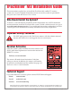
TracVision M3 Installation Guide ® These instructions explain how to install the TracVision M3 satellite TV antenna system on a vessel. Complete instructions on how to use the system are provided in the Quick Start Guide and Receiver User’s Guide. Who Should Install the System? To ensure a safe and effective installation, KVH recommends that a KVH-authorized marine technician install the TracVision M3 system. To find a technician near you, go to www.kvh.com/wheretogetservice.
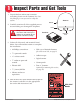
1 Inspect Parts and Get Tools 1. Unpack the box and ensure it contains everything shown on the Contents List. Save the packaging in case you need to reship the system. Antenna Radome 2. Carefully examine all of the supplied parts to ensure nothing was damaged in shipment. Base Always lift the antenna by the silver base and never by the radome or any portion of the internal antenna assembly. Receiver Connector Cover 3. Gather all of the tools and materials listed below.
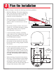
2 Plan the Installation Before you begin, consider the following installation guidelines: • Minimize blockage. The antenna requires a clear view of the sky to receive satellite TV. The fewer obstructions above decks, the better the system will perform. • When choosing a mounting surface, ensure it is wide enough to accommodate the antenna’s base. See illustrations for antenna dimensions.
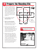
3 Prepare the Mounting Site Antenna Base 15.5" (39.4 cm) 1. Unfold the supplied template and place it onto the mounting surface. Make sure the “FWD” (forward) arrow points toward the bow and is parallel to the vessel’s centerline. You do not need to mount the antenna exactly on the vessel’s centerline, but the antenna’s forward arrow must be parallel to it. 2.8" (7.1 cm) X 5.6" (14.2 cm) 2. Use the template to mark the four hole locations on the mounting surface. 4 x 0.31" ( 0.8 cm) Mounting Holes 3.
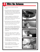
4 Wire the Antenna 1. Clean and dry the antenna mounting surface. 2. Peel off the paper backing from the donutshaped foam seal to expose the adhesive. Then press the foam seal down firmly onto the mounting surface, centered between the antenna mounting holes. 3. Using the supplied 3 mm Allen hex key, remove the connector cover from the antenna’s base. Save the cover and the four M4 cap screws for later use. Foam Seal 4. Route either end of the antenna cable into the vessel.
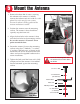
5 Mount the Antenna 1. Remove the three #10-32 screws securing the radome to the antenna. Carefully remove the radome and set it aside in a safe place. Due to the snug fit, some contact between the radome’s sealing gasket and the antenna mechanism is normal. “Forward” Arrow 2. Position the antenna onto the mounting surface. The antenna’s base should rest squarely atop the foam seal. 3. Align the four holes in the antenna’s base with the four holes in the mounting surface.
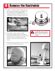
6 Remove the Restraints 1. Using a 7⁄16" socket wrench, remove the two bolts securing the antenna assembly to the base. Be sure to remove both of these shipping restraints, along with the washers and spacers. Save the restraints for future use. Shipping Restraints Bolt Washer Spacer 2. Reinstall the antenna radome. While pressing the radome down onto the base, secure the radome to the base using the three #10-32 screws you removed earlier. The radome’s “TracVision” labels should face fore and aft. 3.
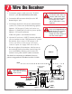
7 Wire the Receiver 1. Connect the antenna cable (A) to the “To KVH Antenna” jack. Do not kink/stress the cable. Do not shorten or extend the antenna cable. Since the antenna cable carries data, power, and communications, the integrity of this cable and its connections is very important. 2. Connect the RF converter cable (B) to the “RF Remote Input” jack. 3. Connect the receiver to the vessel’s entertainment system (TV).
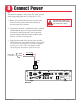
8 Connect Power The receiver requires a 10-16 volts DC (VDC) power input supporting 50 watts (4.2 amps @ 12 VDC). For your own safety, shut down vessel power before you connect the wires. 1. Before you connect the receiver’s power wires, turn off vessel power and test the circuit to ensure no power is present. 2. Connect the receiver’s individual power wires to a dedicated 10-amp or 15-amp circuit breaker.
9 Install the Receiver Once all cables are connected, install the receiver inside the vessel. To avoid overheating, do not block the receiver’s vents. 1. If you wish to mount the receiver, attach the two mounting brackets to the sides of the receiver using three #2-56 screws. Simply screw these fasteners into the receiver’s vent slots. 1⁄4" Fasteners (x4) (not supplied) Bracket #2-56 x 1⁄4" Screws (x3) 2.
11 Test the System Now all you need to do is turn the system ON and ensure everything works properly. 1. Ensure the antenna has a clear view of the southern sky. Power Switch 2. Apply power to the TV and the TracVision system. VHF ANTENNA IN VEHICLE POWER (10-16 VDC) POWER 3. Turn on the power switch on the receiver’s rear panel. SATELLITE IN 4. Wait while the antenna searches the sky for the DIRECTV satellite. Once the antenna finds the satellite, the receiver downloads the program guide.
Things the User Needs to Know • Keep the radome installed on the antenna at all times. The radome protects the antenna’s internal moving parts from wind, rain, and debris. CAUTION: In the unlikely event that you need to remove the radome, remove power from the antenna first because the antenna’s moving parts can cause injury. The owner needs the red Activation Card to activate the receiver. 051099999 051077777 • The receiver must be activated before it can receive DIRECTV programming.
www.kvh.com KVH Industries, Inc. • 50 Enterprise Center • Middletown, RI 02842-5279 U.S.A . • Phone: (401) 847-3327 • Fax: (401) 849-0045 • E-mail: info@kvh.com © Copyright 2005, KVH Industries, Inc. KVH and TracVision are registered trademarks of KVH Industries, Inc.