
Satellite TV System User Manual


5-6
A Guide to TracVision L3
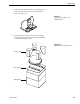
5.4.2 RF Detector/DVB Decoder
Estimated Time to Repair:
1
⁄2 hour
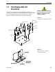
The RF Detector PCB receives operating voltages from both the
CPU board and the IRD (via the RF cable) – Fig. 5-1. Ensure that
all power is turned off before proceeding.
1. Remove the 4 RF board cover screws and washers
from the RF board cover.
2. Remove the RF board cover.
3. Remove 2 RF connectors from the coaxial fittings
on the PCB. Tag the cables to ensure that they are
returned to the same connectors.
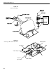
4. Remove the Molex connectors from J3 and J1
– Fig. 5-5.
5. Remove the 4 standoffs – Fig. 5-1. Remove the RF
Detector PCB from the rotating plate.
6. Installation of the replacement RF Detector is the
reverse of this procedure. Be sure that the RF
cables are restored to their original positions. Be
sure that the center conductor pin is centered in
the connector before tightening the collar.
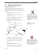
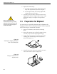
5.4.3 Antenna Gyro Assembly
Estimated Time to Repair: 1 hour
The antenna gyro is mounted on the rear of the antenna reflector
bracket with four locking nuts and washers – Fig. 5-3. Following
the removal and replacement of the antenna gyro assembly, it
will be necessary to calibrate the gyro and restart the system.
Directions for removal, replacement, and calibration follow:
1. Remove the quick release pin from the pivot
bracket – Fig. 5-2.
2. Remove the elevation axis motor shaft from the
linear actuator – Fig. 5-2.
3. Remove the 6 pan head screws from the PCB cover
flanges. Remove the PCB cover – Fig. 5-1.
4. Remove the screw and clamp holding the antenna
gyro cable to the rotating plate. Be sure to save the
cable clamp and screw – Fig. 5-4.
Following the removal and
replacement of the antenna gyro
assembly, it will be necessary to
calibrate the gyro and restart
the system.