
Satellite TV System User Manual


5-5
Maintenance
54-0157 Rev. C
5.4.1 PCB Removal and Replacement
Estimated Time to Repair:
1
⁄2 hour
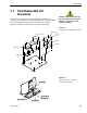
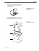
The microprocessor PCB assembly is protected by a cover
fastened to the rotating plate – Fig. 5-1. The cover must be
removed to gain access to the main power fuse and the PCB
assembly.
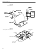
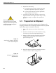
1. Remove the quick release pin from the pivot
bracket – Fig. 5-2.
2. Remove the elevation axis motor shaft from the
linear actuator – Fig. 5-2.
3. Remove the 6 pan head screws from the PCB cover
flanges. Remove the PCB cover – Fig. 5-1.
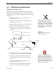
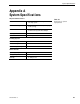
4. Remove cable connectors from PCB. Figure 5-5
illustrates the PCB arrangement and connector
locations.
5. The PCB is mounted to the rotating plate with
9 pan head screws. Remove the screws and PCB.
6. Reverse this process to install the replacement
PCB. Reinstall all cable connectors removed in
Step 4.
7. Carry out all calibration procedures for the
antenna gyro (Section 5.4.3).
8. Reinstall your preferred satellites as detailed in
Section 2.4.1, Installing Your Selected Satellites.
RF Board
PCB
J3
J1
RF Connector to IRD
RF Connector to LNB
Fuse
J5
J11
J9
J2 J1
J4
Gyro
RF Board
Limit Switches
Cable Wrap
Elevation Motor Azimuth Motor
TracVision L3 is equipped with a
5x220 mm, 4-amp, 250 volt fast-
blow fuse, which is mounted on the
PCB. To access and replace the
fuse, follow the directions to remove
the PCB cover and then swap the
blown fuse for a new one.
When carrying out maintenance
on the PCB, be sure to not drop
any of the small screws inside the
mechanism. If a screw is lost within
the baseplate, it must be retrieved
to avoid causing any damage when
the unit rotates.
Figure 5-5
PCB and RF Detector Board
Connector Locations