
Satellite TV System User Manual


5-3
Maintenance
54-0157 Rev. C
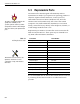
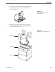
5.4 Field Replaceable Unit
Procedures
The following subsections provide detailed procedures for
repairing or swapping out field replaceable units. The procedures
refer to labeled items presented on the following isometric
diagrams, which are based on KVH assembly drawings.
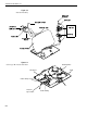
PCB
PCB Cover
Pan Head Screws
Rotating Plate
RF Board
Standoffs
RF Board Cover
RF Cover
Screws
Figure 5-2
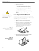
Close-up of Linear Actuator,
Pivot Bracket, and Pin
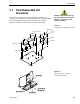
Always lift the Antenna Unit by
the gray baseplate, never by the
radome or any portion of the
antenna assembly!
Figure 5-1
Antenna, PCB, and Rotating Plate