
Satellite TV System User Manual

2-8
A Guide to TracVision L3
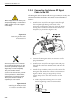
3. Run the Antenna power and data cables from the
Antenna Unit and out through the panel cutout.
4. Run a cable from vehicle’s power (11-16 Vdc)
through the panel cutout.
You are now ready to wire the TracVision L3 system to the
switchplate connectors and vehicle power.
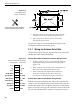
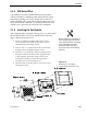
2.3.1 Wiring the Antenna Data Cable
TracVision L3 will not function properly unless you connect the
antenna data cable (Cable #32-0630-30).
Antenna Data Cable-to-Baseplate Terminals Wiring Process
1. Feed the cable up to the roof and through the third
liquid-tight fitting (#3) from the left as pictured in
Figure 2-10.
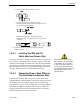
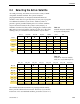
2. Refer to Figure 2-13 for the proper arrangement of
data cable wires within the terminal strip.
3. After connecting the antenna data cable to the
TracVision L3, hook up the other end to the
switchplate as described in the next subsection.
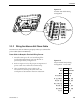
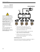
Antenna Data Cable-to-Switchplate Wiring Process
Find the TracVision L3 antenna data cable (Cable #32-0630-30)
where it comes through the panel cutout made earlier. Wire the
antenna data cable to the switchplate connectors as indicated in
Figure 2-14 on the next page. The connector board is etched with
the wire color identification to make the wiring process easier.
Brown/White
Orange/White
White/Brown
White/Orange
White/Gray
Gray/White
Shield
RTN
PC_RXD
PC_TXD
RTN
RF_TXD
RF_RXD
Grnd
4
5
6
7
8
9
10
Figure 2-13
Proper Terminal Strip Wiring
Arrangement – Data Cable
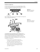
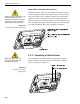
Figure 2-12
Switchplate Panel
Cutout Dimensions
A full-scale panel cutout template
has been provided in Appendix C.