
Satellite TV System User Manual

2-6
A Guide to TracVision L3
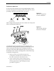
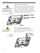
16. Place Antenna Unit on mounting plate and secure
using nuts and washers removed in Step 7.
17. Proceed to Section 2.3, “Wiring the TracVision L3
System,” to wire the TracVision L3 system. The
radome will be placed back on the baseplate using
the hardware removed in Step 2 after wiring and
initializing the system.
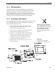
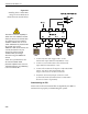
2.3 Wiring the TracVision L3 System
The following sections provide instructions for properly wiring
the Antenna Unit to the IRD and to vehicle power.
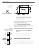
Tips for Safe and Successful Wiring within
the TracVision L3 Baseplate
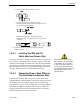
• When attaching cables to the TracVision L3
terminal connector strips, make sure the insulation
is stripped back approximately
1
⁄4" (6 mm) as
illustrated in Figure 2-8. Twist the wires gently to
help achieve a good connection. Do not pinch
insulation inside the connector.
• After attaching the power and data cables to the
appropriate terminal connector strips, tug gently
to ensure a firm connection.
• After attaching cables within the TracVision L3
baseplate, eliminate any unnecessary slack in the
cables before tightening the liquid-tight fittings.
• Run the RF signal cable into the baseplate last. It
will help keep the power and data cables clear of
the antenna and LNB.
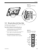
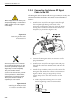
• After hooking up all of the wiring and removing any
slack, slowly rotate the antenna while raising and
lowering the reflector to make certain that the cables
are all clear of any moving elements as pictured in
Figure 2-9.
• Check to be certain that the elevation axis actuator
motor shaft (pictured in Section 5, Maintenance,
Figure 5-2) clears all cable connections.
• Completely seal all rooftop cable access holes.
Figure 2-9
Moving the Antenna Reflector
Figure 2-8
Proper Wire-to-Terminal
Connection
DO NOT leave an extra length of
cable within the baseplate as a
service loop. All service loops
should be stored within the
vehicle’s cable access.