Satellite Television A Guide to TracVision L3 owner’s manual ® KVH TracVision L3 • Installation Instructions • User’s Guide • Technical Manual
Congratulations! You have selected one of the most advanced land-mobile satellite tracking systems available today. KVH® Industries’ TracVision® L3 is designed for use with European and North American DVBcompatible satellite services as well as DIRECTV®. This manual provides detailed instructions on the proper installation, use, and maintenance of your TracVision L3 system.
TracVision® and KVH® are registered trademarks of KVH Industries, Inc. DIRECTV® is an official trademark of DIRECTV, Inc., a unit of GM Hughes Electronics. DISH™ Network is an official trademark of EchoStar Communications Corporation. ExpressVu is a property of Bell ExpressVu, a wholly owned subsidiary of Bell Satellite Services.
Table of Contents 1 Introduction . . . . . . . . . . . . . . . . . . . . . . . . . . . . . . .1-1 1.1 Digital Satellite Television . . . . . . . . . . . . . . . . . . . . . . . . . . . . . .1-1 1.2 TracVision L3 System Overview . . . . . . . . . . . . . . . . . . . . . . . . .1-2 1.2.1 TracVision L3 Components . . . . . . . . . . . . . . . . . . . . . . . . .1-3 1.2.2 Integrated Receiver Decoder . . . . . . . . . . . . . . . . . . . . . . .1-4 1.3 Materials Provided with TracVision L3 . . . . . . . .
3 Using Your TracVision L3 . . . . . . . . . . . . . . . . . . . . . . .3-1 3.1 Turning on the System . . . . . . . . . . . . . . . . . . . . . . . . . . . . . . . .3-1 3.2 Changing Channels and Switching to the Second Satellite . . .3-2 3.3 Watching TV on the Move and at Rest . . . . . . . . . . . . . . . . . . . .3-3 4 Troubleshooting . . . . . . . . . . . . . . . . . . . . . . . . . . . . .4-1 4.1 Causes and Remedies for Common Operational Issues . . . . . .4-1 4.1.
Appendix A System Specifications . . . . . . . . . . . . . . . . . .A-1 Appendix B Functional Block Diagram . . . . . . . . . . . . . . . .B-1 Appendix C Switchplate Template . . . . . . . . . . . . . . . . . .C-1 Appendix D Predefined Satellite Configurations . . . . . . . . .D-1 Appendix E Startup Data Sequence . . . . . . . . . . . . . . . . . .E-1 Appendix F Maintenance Port Parser Commands . . . . . . . . .F-1 F.1 System Commands . . . . . . . . . . . . . . . . . . . . . . . . . . . . . .
Figure 2-11 Cable Overlap within the TracVision L3 Baseplate . . . . . . .2-7 Figure 2-12 Switchplate Panel Cutout Dimensions . . . . . . . . . . . . . . . .2-8 Figure 2-13 Proper Terminal Strip Wiring Arrangement – Data Cable . . . . . . . . . . . . . . . . . . . . . . . . . . . . . . . . . .2-8 Figure 2-14 Antenna Data Cable Wiring Arrangement . . . . . . . . . . . . .2-9 Figure 2-15 Proper Terminal Strip Wiring Arrangement – Power Cable . . . . . . . . . . . . . . . . . . . . . . . . . . . . . .
List of Tables Table 1-1 Available European Satellite Pairs (European LNB Required) . . . . . . . . . . . . . . . . . . . . . . .1-1 Table 1-2 Available N. American Satellite Pairs (U.S.-style LNB required0 . . . . . . . . . . . . . . . . . . . . . . .1-2 Table 1-3 TracVision L3 Packing List . . . . . . . . . . . . . . . . . . . . . . .1-4 Table 2-1 Installation Process . . . . . . . . . . . . . . . . . . . . . . . . . . . .2-1 Table 2-2 Kitpack Contents . . . . . . . . . . . . . . . . . . . . . .
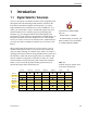
Introduction 1 Introduction 1.1 Digital Satellite Television Your new TracVision L3 satellite antenna is fully compatible with the Digital Video Broadcasting (DVB) satellites, which use the international standard for digital TV transmission, as well as Digital Satellite Service (DSS) services, such as DIRECTV®. As a result, you will be able to receive and decode signals from your chosen satellite services with the proper programming and hardware (e.g., the Integrated Receiver Decoder [IRD]).
A Guide to TracVision L3 Table 1-2 Available N. American Satellite Pairs (U.S.-style LNB required) DSS_101 DSS_110 DSS_119 Echo_61 Echo_110 Echo_119 ü ü ü Echo_148 Expressvu ü ü ü ü ü ü ü DSS_101 DSS_110* DSS_119 ü Echo_61 ü ü Echo_110 Echo_119 Echo_148 ü Expressvu ü ü ü ü ü ü * Contact KVH or DIRECTV for complete details on tracking and receiving signals from DSS_110. 1.
Introduction System specifications and a functional block diagram are provided in Appendices A and B, respectively. 1.2.1 TracVision L3 Components The Antenna Unit includes the antenna positioning mechanism, signal front end, power supply and control elements. The antenna is a parabolic dish mounting a low noise block (LNB) converter with built-in preamplifier. The European configuration includes a single port LNB while the North American system uses a dual-output LNB.
A Guide to TracVision L3 1.2.2 Integrated Receiver Decoder The dual-output LNB in the North American systems allows two IRD/TV pairs to be connected directly to the antenna. Three or more pairs can be connected to the system if an active multiswitch is used. Section 2.3.6, “Connecting the Antenna RF Signal Cable to the IRD,” provides installation directions for each of these options.
Introduction 1.3.1 Additional Materials Required for TracVision L3 Use To make full use of your new TracVision L3 and receive satellite TV on the road, you will need to provide/purchase the following: • Television • Appropriate IRD for your selected satellite TV service, and • Sealing materials to weatherproof cable holes and seal mounting plate. 54-0157 Rev.
Installation 2 Installation TracVision L3 is designed for simple installation and setup. Just follow these easy steps: Step Refer to Section... 1. Choose the hardware locations 2.1 2. Mount the Antenna Unit 2.2 3. Wire system components 2.3 4. Select active satellite 2.4 5. Set the skew angle (Europe only) 2.5 6. Check out system 2.6 7. Configure for remote dish use 2.
A Guide to TracVision L3 2.1 Always lift the Antenna Unit by the gray baseplate, never by the radome or any portion of the antenna assembly! Choosing the Best Location • The ideal antenna site has a clear view of the horizon/satellite all around. • Keep the antenna clear of any obstructions on the roof (e.g., air conditioners). • Consider the location of the antenna relative to the location of any equipment or necessary wiring within the vehicle.
Installation Figure 2-1 Proper Orientation of the Antenna Unit V Cen ehicle terli ne Figure 2-2 Elevation Shipping Restraint 4. While baseplate is in place, mark location(s) on roof for cable access to permit convenient cable access to the liquid-tight fittings on the back of the baseplate. 5. Cut the tie-wraps holding the foam elevation shipping restraint to the elevation axis motor shaft (pictured in Figure 2-2) and remove the restraint. 6.
A Guide to TracVision L3 the appropriate fasteners, two flexible wings allow the rear mounting bolts to attach to the antenna baseplate. These may be angled upward to ensure a secure mounting, as shown in Figure 2-4. Figure 2-4 Mounting the Unit on a Curved Surface Antenna Baseplate bolts to this “wing,” which can remain horizontal. Mounting Plate Wing Mounting Plate can be tightened down to conform to a curved surface. 10.
Installation 13. Reposition mounting plate over adhesive and attach using 3⁄16" (5 mm)-diameter rivets (or appropriate fasteners). Seal all rivet heads and edges with silicone. 14. Drill cable access hole(s) in vehicle. 15. When unit is installed with connectors facing the rear of the vehicle, the drain holes are located as shown in Figure 2-6. Figure 2-6 Connectors Facing Rear of Vehicle – Factory-drilled Drain Hole Locations Front of Vehicle Factory-drilled Drain Hole Positions 15a.
A Guide to TracVision L3 16. Place Antenna Unit on mounting plate and secure using nuts and washers removed in Step 7. 17. Proceed to Section 2.3, “Wiring the TracVision L3 System,” to wire the TracVision L3 system. The radome will be placed back on the baseplate using the hardware removed in Step 2 after wiring and initializing the system. 2.3 Wiring the TracVision L3 System The following sections provide instructions for properly wiring the Antenna Unit to the IRD and to vehicle power.
Installation TracVision L3 Cable Ports On one side of the baseplate are four liquid-tight fittings, which serve the dual purpose of relieving strain on the cables as well as providing a tight seal around the cable access ports. Figure 2-10 Cable Port Assignments (Exterior of Baseplate) RF (#1) RF (#2) Data (#3) Power (#4) Used only with N. American Systems When wiring is done properly, the sets of cables will overlap each other, as illustrated in Figure 2-11.
A Guide to TracVision L3 Figure 2-12 Switchplate Panel Cutout Dimensions 3.82" (97 mm) /32" (3 mm) dia .32" (8 mm) 2.36" (60 mm) A full-scale panel cutout template has been provided in Appendix C. 3 .16" (4 mm) Panel Cutout 2.05" (52 mm) 3.19" (81 mm) 3. Run the Antenna power and data cables from the Antenna Unit and out through the panel cutout. 4. Run a cable from vehicle’s power (11-16 Vdc) through the panel cutout.
Installation Figure 2-14 Antenna Data Cable Wiring Arrangement BLU/WHT Not Used WHT/BLU Not Used BRN/WHT PC GND WHT/BRN PC TXD ORG/WHT PC RXD WHT/ORG GRY/WHT WHT/GRY GRN/WHT WHT/GRN RF GND Data Cable to Antenna RF TXD RF RXD Not Used Not Used 2.3.2 Wiring the Antenna Unit Power Cable TracVision L3 will not function properly unless you connect the power cable (Cable #32-0590-30). Power Cable-to-Baseplate Terminals Wiring Process 1.
A Guide to TracVision L3 Power Cable-to-Switchplate Wiring Process Before connecting the Antenna Unit to vehicle power, remove the appropriate vehicle fuse to prevent a short circuit. After connecting to vehicle power, replace the fuse. Figure 2-16 Power Cable Wiring Arrangement Find the TracVision L3 power cable (Cable #32-0590-30) where it comes through the panel cutout made earlier. Wire the Antenna Unit power cable to the switchplate connectors as indicated in Figure 2-16.
Installation 2.3.4 IRD Ground Wire A grounding wire (Cable #32-0583-50) has been provided to connect your IRD to a suitable ground and protect the system. Attach the grounding wire to any suitable screw on the rear panel of the IRD with a good contact with the IRD chassis. The other end should be connected to a suitable ground, such as the vehicle’s power ground wire connected to the switchplate. 2.3.
A Guide to TracVision L3 2.3.6 Connecting the Antenna RF Signal Cable to the IRD When shipped from the factory, the #1 liquid-tight fitting is sealed with a rubber stopper. Leave the stopper in the fitting. Figure 2-19 Connecting the RF Cable to TracVision L3 The RF signal cable is fitted with an F-type connector at only one end and should be attached to TracVision L3 and the IRD as follows: 1.
Installation B. Twist and break off connector body. Twist C. Use the Augat tool to strip the center conductor and trim back the overall jacket. Do not cut through the braid. 0.25" (6 mm) 0.25" (6 mm) D. Slide connector body onto the prepared cable. Slide the compression fitting up into the connector body. Use Augat tool to snap on the connector. 5. Attach the cable to the IRD connector labeled SATELLITE IN. 2.3.6.
A Guide to TracVision L3 Figure 2-21 Installing Three or More IRDs Using an Active Multiswitch (North American Systems Only) TracVision L3 RF Connectors RF1 RF2 DC Power DC In TracVision L3 has the capability to switch from one satellite to another when you choose TV channels that are carried by your two selected satellites. However, the use of an active multiswitch may interfere with the 22 KHz tone sent by DIRECTV+ IRDs to the antenna.
Installation 2.4 Selecting the Active Satellite As noted previously, TracVision L3 can track a variety of DVBcompatible and DSS satellites. The system contains a preprogrammed library of European and North American satellites. It also has two open slots that you may use to program two additional satellites of your choice. Tables 2-3 and 2-4 provide a grid of possible satellite pairs. Two of these satellites may be selected to reside in the system’s active memory as Satellites A and B.
A Guide to TracVision L3 “Programming User-defined Satellites.” After configuring the userdefined satellites, return to the satellite installation process in Section 2.4.1, “Installing Your Selected Satellites.” 2.4.1 Installing Your Selected Satellites When you first connect to the system, it is programmed with the factory default satellite assignments: The satellite configuration on your IRD must match the satellite setting on the TracVision L3 system.
Installation Installing the Satellite of Choice Once the data connection has been made between the PC and the TracVision L3, you must assign the satellites you wish to have in the satellite pair. On the maintenance screen, put the antenna in Idle Mode by typing HALT, then enter the SATINSTALL command: Table 2-5 Satellite Installation Names Satellite Install Name European Satellites ASTRA1 19.2˚E ASTRA1 ASTRA2N 28.2˚E ASTRA2N Command: SATINSTALL,, ASTRA2S 28.
A Guide to TracVision L3 • Transponder information for each of the following polarizations/frequencies: - vertical high & vertical low - horizontal high & horizontal low • Transponder information includes: - frequency - symbol rate - FEC code, and - network ID (in hexidecimal format) • Decoder type This information can be obtained from your satellite service provider or from sites on the Internet, such as www.satcodx.com.
Installation After entering the SATCONFIG command, you must turn on the DEBUG mode by typing @DEBUGON.
A Guide to TracVision L3 After entering this information, it is necessary to save these settings. To do so, type: @SAVE,A (or @SAVE,B if this data is for Satellite 2) @DEBUGOFF After completing this process, restart the system by either cycling power or typing ZAP in the maintenance screen. One of your user-defined satellite options has now been added to the TracVision L3 satellite library. This option will now be available the next time the SATINSTALL command is given.
Installation Based on this information, the data entered via the PC would look like this, assuming that YOURSAT 101 would be Satellite A: SATCONFIG,USER1,7,W,3,L @DEBUGON @SATCONFIG,A,98,11966,27500,34,0x0800,H,H,3 @SATCONFIG,A,98,11823,27500,34,0x0800,V,H,3 @SATCONFIG,A,98,00000,27500,34,0x0000,V,L,3 @SATCONFIG,A,98,00000,27500,34,0x0000,H,L,3 @SAVE,A @DEBUGOFF ZAP 2.5 Setting the Skew Angle (European Systems Only) The Antenna LNB skew angle must be adjusted to optimize channel reception.
A Guide to TracVision L3 2.6 Checking Out the System To complete the TracVision L3 installation, it will be necessary to verify that the system functions properly. Critical to ensuring that the system is configured and operating properly is to check the system startup routine to ensure that the system is operating within normal parameters. To do so, it is necessary to connect a PC to the terminal maintenance port.
Owner’s Manual and Installation/Service Guide system is receiving and decoding the signals properly. If possible, view both horizontally and vertically polarized channels. 2. Select several channels from your second active satellite service to confirm that the system is receiving and decoding the signals properly. If possible, view both horizontally and vertically polarized channels. Completing the Installation Once the system has been installed and is operating properly, replace the radome. 2.
Using Your TracVision L3 3 Using Your TracVision L3 For TracVision L3 to receive the satellite signals, the antenna must have a clear line of sight to the satellite. If you only receive intermittent signals or the antenna cannot find the satellite, check around your vehicle for any objects that could be blocking the signal, such as trees, buildings, highway overpasses, etc. Figure 3-1 Be Aware of Objects that Might Block the Satellite Signals 3.
A Guide to TracVision L3 3.2 The satellite configuration on your IRD must match the satellite setting on the TracVision L3 system. Satellite A on the TracVision L3 must be the same satellite as IRD Alternative 1 (or A, based on your IRD) and must be assigned the IRD DiSEqC 1 setting. Satellite B on the TracVision L3 must be the same satellite as IRD Alternative 2 (or B, based on your IRD) and must be assigned the IRD DiSEqC 2 setting. Refer to your IRD user manual for complete instructions for your IRD.
Using Your TracVision L3 control. If you are a DIRECTV subscriber, but do not have a DSS Plus IRD, use the maintenance port switching option previously described. EchoStar and ExpressVu Satellite Subscribers EchoStar and ExpressVu subscribers will need to use the maintenance port switching method. 3.3 Watching TV on the Move and at Rest TracVision L3 is designed to operate as efficiently and as reliably as possible both when your vehicle is in motion and parked.
A Guide to TracVision L3 begin tracking the satellite again. This convenient feature is ideal for when a vehicle is parked for a short time or idling and passengers want to watch TV. KVH recognizes that some customers may not want to take advantage of this convenient feature. In this case, it is possible to disable Sleep Mode using a simple software command as follows: 1. Connect a laptop computer to the system used the maintenance port and a terminal emulation program, as described in Section 2.4.
Troubleshooting 4 Troubleshooting The troubleshooting matrix shown in Table 4-1 identifies some trouble symptoms, their possible causes, and references to troubleshooting solutions. zo n rin Inc orr ec ing du me Ve h icl et urn sa tel lite co ve ra do on ng oli Ou tsi de np o X X Intermittent picture for short intervals X System works at rest but not on the move X System will not find satellite X X X X X X X X X X X X X X X X Snowy television picture 4.
A Guide to TracVision L3 4.1.1 Blown Fuse or Improper Wiring If the Antenna Unit is installed but entirely non-responsive, there are three key factors to check as part of the troubleshooting process: 1. Blown Fuse – The Antenna Unit is equipped with a fuse mounted on its CPU Board. If this fuse has blown or been broken, the Antenna Unit will not operate. Refer to Section 5.4.1, “PCB Removal and Replacement,” for details on the fuse location and how to access the CPU Board. 2.
Troubleshooting 4.1.4 Dew or Rain Pooling on Dome Dew or rain can occasionally pool on the top of the radome. While this moisture will usually be dispersed when the vehicle is in motion, it can disrupt the signal while the vehicle is at rest. This issue can be minimized with two approaches: 1. Spray the dome with hosed water to remove the dew from the dome surface. 2. Periodically apply liquid dish detergent to the dome surface. Wipe the full-strength detergent on the dome and allow it to dry.
A Guide to TracVision L3 4.1.8 Using a Passive Multiswitch (North American Systems Only) An active multiswitch must always be used to connect the TracVision L3 system to multiple IRDs. Refer to Section 2.3.6, “Connecting the Antenna RF Signal Cable to the IRD” for directions on proper multiswitch/multiple IRD cabling. 4.2 IRD Troubleshooting The IRD that was provided with your satellite television service may also be the cause of less-than-ideal operation. 4.2.1 IRD Wiring Refer to Section 2.3.
Troubleshooting The diagnostics procedure requires terminal emulation software such as PROCOMM, Windows Terminal, or Windows 95/98 Hyperterminal. Use the settings appropriate to your application. 1. Connect one end of the PC data cable to the DB9 connector on the switchplate. Connect the other end to the serial port on the PC (a 9-pin/25-pin connector adapter may be needed for some PCs). 2.
Maintenance 5 Maintenance 5.1 Warranty/Service Information KVH Industries, Inc. warrants the KVH product purchased against defects in materials for a period of TWO (2) years and against labor costs for a period of ONE (1) year from the date of original retail purchase by the original purchaser.
A Guide to TracVision L3 5.3 To help us continually improve the quality and reliability of our systems, please return any failed component to KVH or KVH Europe after you receive your replacement part. Table 5-1 Field Replaceable Units Should the fuse ever need to be replaced, TracVision L3 uses a 5x20mm, 4-amp, 250-volt fastblow fuse. Replaceable Parts TracVision L3 has been designed with durability and low maintenance in mind.
Maintenance 5.4 Field Replaceable Unit Procedures The following subsections provide detailed procedures for repairing or swapping out field replaceable units. The procedures refer to labeled items presented on the following isometric diagrams, which are based on KVH assembly drawings.
A Guide to TracVision L3 Figure 5-3 Antenna Assembly Wing Screw and Washer LNB Clamp Antenna Gyro Cable Locking Nuts and Washers Antenna Gyro Reflector Bracket LNB Styles N.
Maintenance 5.4.1 PCB Removal and Replacement Estimated Time to Repair: 1⁄2 hour The microprocessor PCB assembly is protected by a cover fastened to the rotating plate – Fig. 5-1. The cover must be removed to gain access to the main power fuse and the PCB assembly. 1. Remove the quick release pin from the pivot bracket – Fig. 5-2. When carrying out maintenance on the PCB, be sure to not drop any of the small screws inside the mechanism.
A Guide to TracVision L3 5.4.2 RF Detector/DVB Decoder Estimated Time to Repair: 1⁄2 hour The RF Detector PCB receives operating voltages from both the CPU board and the IRD (via the RF cable) – Fig. 5-1. Ensure that all power is turned off before proceeding. 1. Remove the 4 RF board cover screws and washers from the RF board cover. 2. Remove the RF board cover. 3. Remove 2 RF connectors from the coaxial fittings on the PCB. Tag the cables to ensure that they are returned to the same connectors. 4.
Maintenance 5. Remove the Molex connector from J11 on the CPU board – Fig. 5-5. 6. Remove the 4 nuts and washers and take the gyro off of the bracket. 7. Remove the antenna gyro gasket. 8. Replacement is the reverse of this procedure. Antenna Gyro Calibration 1. Connect a PC to the communications port as described in Section 4.4, “Computer Diagnostics.” 2. Type HALT while the system is performing the limit switch initialization routine.
A Guide to TracVision L3 6. Replace the LNB clamp: A. For North American LNBs, tighten the clamp fully. The replacement process is complete. B. For European LNBs, do not fully tighten the clamp and proceed to step 7. 7. Carefully turn the LNB so that the scribe mark is aligned with the skew angle noted in Step 1. Fully tighten the clamp to complete the replacement process.
Maintenance 5. Secure the elevation restraint by wrapping two tiewraps through the open end of the restraint as shown in Figure 5-9. Figure 5-9 Securing the Elevation Axis Shaft Restraint 6. Place the entire Antenna Unit into its shipping containing using the original packaging material, as illustrated in Figure 5-10. Figure 5-10 Repackaging the TracVision L3 Foam Inserts Base Support Shipping Box 54-0157 Rev.
System Specifications Appendix A System Specifications Physical Characteristics Power 11-16 volts DC @ 2.5 amps nominal, 3.5 amps peak Dimensions/Weight 32" (81 cm) wide x 14.5" (37 cm) high, 33 lbs (15 kg) LNB European System: Single Output N. American System: Dual Output Tracking Better than 30˚/sec Maintenance Port 9600 bps, 8,N,1,EIA, RS232 Table A-1 TracVision L3 System Specifications Pointing System Elevation Range 15˚ to 75˚ Azimuth Range 720˚ Position Repeatability 0.
Functional Block Diagram Appendix B Functional Block Diagram TracVision L3 Antenna Unit Components/Wiring In-vehicle Components Terminal Connectors TV LNB Antenna Sensor Elevation Mechanism Azimuth Mechanism IRD RF1 RF2 (N. American Systems Only) RF DVB Decoder Switchplate DB9 Connector Power Switch Vehicle Power +12v DC Elevation Motor Maint. CPU/Motor Driver/ Power Supply Azimuth Motor Power Elevation Limit Switch Azimuth Limit Switch Cable Assignments RF1.........................
3 /32" (3 mm) dia .32" (8 mm) 2.36" (60 mm) .16" (4 mm) Panel Cutout Appendix C Switchplate Template 54-0157 Rev. C 3.82" (97 mm) 2.05" (52 mm) 3.
Predefined Satellite Configurations Appendix D Predefined Satellite Configurations As noted previously, your TracVision L3 comes programmed with the satellite configurations for seven European and eight North American satellite services. For your reference, those configurations are listed below. These configurations are current as of September 15, 2000, and are subject to change by the satellite service providers.
A Guide to TracVision L3 North American Satellites D-2 Satellite F,S,C,ID,P,B,D ExpressView 12603,20000,56,0X0100,V,U,3 12603,20000,56,0X0100,V,U,3 12384,20000,56,0X0100,H,U,3 12384,20000,56,0X0100,H,U,3 Echostar 61 12577,20000,34,0X1002,V,U,3 12577,20000,34,0X1002,V,U,3 12358,20000,34,0X1002,H,U,3 12358,20000,34,0X1002,H,U,3 Echostar 110 12456,20000,34,0X1006,V,U,3 12456,20000,34,0X1006,V,U,3 12383,20000,34,0X1006,H,U,3 12383,20000,34,0X1006,H,U,3 Echostar 119 12374,20000,34,0X1004,V,U,3 12374,
Startup Data Sequence Appendix E Startup Data Sequence The data on the following pages presents a standard startup data sequence registered by the TracVision L3. This sequence can be recorded using the data port and a PC. ?PGM KVH TracVision L3 Rev X - Version X.
A Guide to TracVision L3 *** Entering Tracking *** RF: S,B,H,U,V +POS: 231.5 26.2 1334 +POS: 231.3 25.8 2023 +POS: 230.6 24.4 2741 RF: Freeze DAC = -00652 +POS: 230.1 23.9 2829 *** Network ID Check ***---------------------Comparing the tracked satellite’s network ID to the +POS: 230.0 23.5 2843 selected satellite’s network ID RF: Y,0X1004---------------------------------Indicates positive satellite identification *** Tracking DSS_119 ***---------------------Identifies satellite currently tracked +POS: 229.
Maintenance Port Parser Commands Appendix F Maintenance Port Parser Commands TracVision L3 system parser commands are parsed when the system receives an ASCII carriage return (Hex 0D). An ASCII line feed (Hex 0A) is permitted but is ignored in any transmitted command. All system responses are terminated with an ASCII carriage return followed by a line feed and ending with either an acknowledge character (ASCII > (Hex 3E)) or a not-acknowledge character (ASCII ? (Hex 3F)).
A Guide to TracVision L3 Calibrate Gyro Function: performs azimuth and elevation calibration Command: CALGYRO Argument: none Response: echoes command and calibrates gyro Find Skew Angle for Currently Selected Satellite Function: calculates necessary LNB skew based on latitude, longitude, and selected satellite Command: SKEWANGLE* Argument: none Response: displays skew angle * Before this command can function properly, you must perform the GPS Position command detailed in Section F.
Maintenance Port Parser Commands Elevation Angle Function: commands a manual elevation angle that the mechanism moves to Command: EL,xxx (range is 100-850) Argument: desired elevation angle of the mechanism relative to up, 10.0°-85.0° Response: echoes the command; mechanism moves at a fixed velocity Azimuth CW Step Function: commands a 0.1 deg CW manual step in azimuth angle Command: 6 Argument: none Response: echoes the command Azimuth CCW Step Function: commands a 0.
A Guide to TracVision L3 F.3 Operational Commands To execute the following commands, first put the Antenna Unit in idle mode by typing HALT and pressing “ENTER.” After the system comes to a halt, type DEBUGON and press “ENTER” to enter programming mode.
Maintenance Port Parser Commands Analog Signal Strength Report Function: reports signal strength from RF detector circuit in A/D counts (000-FFF Hex) Command: SIGLEVEL Argument: none Response: Signal Strength = xxxx F.
A Guide to TracVision L3 Set RF Tracking Parameters Function: sets RF tracking parameter Command: @SATCONFIG,X,N,F,S,C,ID,P,B,D Response: Echoes the input data Where: @SATCONFIG = directs data to the RF Board X = satellite location A or B N = satellite table # (98 & 99 are slots for userconfigured satellites) F = frequency in MHz (either 00000 or a range from 10700 - 12700) S = the satellite transponder symbol rate in Mbit/second (01000 - 29999) C = the FEC code (e.g.
Maintenance Port Parser Commands Select Active Satellite Function: switch antenna tracking to/from satellite A and B Command: @L,x Where: x = A or B (as defined during the SATINSTALL process) Table F-6 Installation Commands Set/Report GPS Position Function: reports or sets default GPS position Command: GPS GPS,XX,D,YYY,E Response: GPS = XXD YYYE GPS: XXD YYYE Where: XX = latitude (0-90) D = S (South) or N (North) YYY = longitude (0-180) E = E (East) or W (West) Report Satellite Names
A Guide to TracVision L3 Configure Longitude of a User-configurable Satellite Function: configures one of the user-configurable satellites with the longitude provided Command: SATCONFIG,USERX,YYY,Z,D,L Response: If valid pair, echoes the input data If invalid pair, returns error message Where: X = 1 or 2 YYY = longitude (0-180) Z = E (East) or W (West) D = decoding type (0=test, 1=DSS-A, 2=DSS-B, 3=DVB) L = LNB polarization (c=circular, l=linear) F.
KVH Industries Limited Warranty TracVision L3 Limited Warranty on Hardware KVH Industries, Inc. warrants the KVH product purchased against defects in materials for a period of TWO (2) years and against labor costs for a period of ONE (1) year from the date of original retail purchase by the original purchaser.
TVL3 O/M Cover 5/00 ® KVH Europe A/S KVH Industries, Inc. 50 Enterprise Center Middletown, RI 02842 U.S.A. Phone: (401) 847-3327 Fax: (401) 849-0045 E-Mail: info@kvh.com Internet: http://www.kvh.com Ved Klaedebo 12 2970 Hoersholm Denmark Phone: +45 45 160 180 Fax: +45 45 867 077 E-Mail: info@kvh.dk Internet: http://www.kvh.com KVH®, and TracVision® are registered trademarks of KVH Industries, Inc.