Satellite Television A Guide to TracVision L2 owner’s manual • KVH TracVision L2 • Installation Instructions User’s Guide Technical Manual ® •
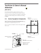
TracVision L2 Owner’s Manual Addendum (ECO #6119) The following information applies to Revision A of the TracVision L2 Owner’s Manual (KVH Part Number 54-0195). A protective cover has been added to the switchplate to guard against damaging electrostatic discharges (ESD), which may occur during installation. 2.
Appendix C Switchplate Template 2" 2.5" 54-0195 Addendum to Rev.
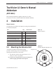
A Guide to TracVision L2 – ADDENDUM TracVision L2 Owner’s Manual Addendum (ECO #6040) The following information applies to Revision A of the TracVision L2 Owner’s Manual (KVH Part Number 54-0195). 2 Installation Kitpack Contents Two plugs have been added to the kitpack for sealing the predrilled holes in the antenna baseplate. Part Qty. KVH Part No.
Congratulations! You have selected one of the most advanced land-mobile satellite tracking systems available today. KVH® Industries’ TracVision® L2 is designed for use with DIRECTV®, DISH Network™, and ExpressVu. This manual provides detailed instructions on the proper installation, use, and maintenance of your TracVision L2 system.
TracVision® and KVH® are registered trademarks of KVH Industries, Inc. DIRECTV® is an official trademark of DIRECTV, a unit of GM Hughes Electronics Corporation. DISH Network™ is an official trademark of EchoStar Communications Corporation. ExpressVu is a property of Bell ExpressVu, a wholly owned subsidiary of Bell Satellite Services.
Table of Contents 1 Introduction . . . . . . . . . . . . . . . . . . . . . . . . . . . . . . .1-1 1.1 Digital Satellite Television . . . . . . . . . . . . . . . . . . . . . . . . . . . . . .1-1 1.2 TracVision L2 System Overview . . . . . . . . . . . . . . . . . . . . . . . . .1-1 1.2.1 TracVision L2 Components.....................................................1-2 1.2.2 Integrated Receiver/Decoder (IRD) ........................................1-2 1.3 Materials Provided with TracVision L2 . . . . . .
3.2.1 Using the IRD for Satellite Selection ......................................3-3 3.2.2 Using the Switchplate for Satellite Selection ..........................3-3 3.2.2.1 The Status Indicator . . . . . . . . . . . . . . . . . . . . . . . . . . . .3-3 3.3 Turning Off the System . . . . . . . . . . . . . . . . . . . . . . . . . . . . . . . .3-4 3.4 Watching Television . . . . . . . . . . . . . . . . . . . . . . . . . . . . . . . . . .3-4 4 Troubleshooting . . . . . . . . . . . . . . . . . . . . .
5.4.2 Antenna Gyro Assembly.........................................................5-6 5.4.3 Antenna LNB Replacement ....................................................5-8 5.5 Preparation for Shipment . . . . . . . . . . . . . . . . . . . . . . . . . . . . .5-10 Appendix A System Specifications . . . . . . . . . . . . . . . . . .A-1 Appendix B Comprehensive TracVision L2 System Wiring Diagram . . . . . . . . . . . . . . . . . . . . . . .B-1 Appendix C Switchplate Template . . . . . . . . . . . . .
Figure 2-9 Rotating Plate Shipping Restraint Storage . . . . . . . . . . . .2-7 Figure 2-10 TracVision L2 Shipping Restraints (Storage Position) . . . .2-7 Figure 2-11 Switchplate Cutout Dimensions . . . . . . . . . . . . . . . . . . . .2-8 Figure 2-12 Antenna Baseplate Connectors . . . . . . . . . . . . . . . . . . . .2-8 Figure 2-13 Switchplate Connectors . . . . . . . . . . . . . . . . . . . . . . . . . .2-9 Figure 2-14 Installing Three or Four IRDs Using an Active Multiswitch . . . . . . . .
Table 3-1 Status Indicator Conditions . . . . . . . . . . . . . . . . . . . . . .3-3 Table 4-1 Troubleshooting Matrix . . . . . . . . . . . . . . . . . . . . . . . . .4-1 Table 5-1 Field Replaceable Units . . . . . . . . . . . . . . . . . . . . . . . .5-2 Table A-1 TracVision L2 System Specifications . . . . . . . . . . . . . . .A-1 Table F-1 System Commands . . . . . . . . . . . . . . . . . . . . . . . . . . . .F-1 Table F-2 Manual Positioning Commands . . . . . . . . . . . . . . . . . . .
Introduction 1 Introduction 1.1 Digital Satellite Television DIRECTV®, DISH Network™, and ExpressVu systems transmit digital audio and video data from land-based transmitters to a satellite “parked” above the equator. Each satellite relays the signals in spot beams covering the continental United States and contiguous waters. TracVision L2 automatically identifies, locks onto, and tracks signals from the appropriate satellite, both while your vehicle is at rest and in motion. 1.
A Guide to TracVision L2 1.2.1 TracVision L2 Components The antenna unit includes the antenna positioning mechanism, signal front end, power supply and control elements. These elements include antenna drive controls and mechanisms, the cable wrap subassembly, antenna gyro sensor, power conditioning and regulating circuits, and the RF detector. The antenna is a parabolic dish mounting a dual-output low noise block (LNB) converter with built-in preamplifier.
Introduction 1.3.1 Additional Materials Required for TracVision L2 Use To make full use of your new TracVision L2 and receive satellite TV, you will need to provide/purchase the following: • Television • Appropriate IRD for your selected satellite TV service 54-0195 Rev. A You can purchase and activate an IRD directly from KVH! Call KVH at 1-888-584-4163 for details.
Installation 2 Installation TracVision L2 is designed for simple installation and setup. Just follow these easy steps: Step Refer to Section... 1. Choose the antenna location 2.1 2. Mount the antenna unit 2.2 3. Connect the system components 2.3 4. Activate the IRD 2.4 5. Check out the system 2.5 Tools and Materials Required • Electric drill • 3 • #2 Phillips and #0 flat tip screwdrivers • RG-6 or RG-11 (75 ohms) RF cable (if installing two RF cables - refer to Section 2.3.
A Guide to TracVision L2 Kitpack Contents Table 2-2 lists the materials provided in the kitpack. Table 2-2 Kitpack Contents Part KVH Part No. Switchplate Assembly 1 02-1236-01 Tie-wraps 5 22-0013 RJ11 Handset Cable 1 32-0724-25 Clam Shell Ventilator 1 19-0230 #6 x 3⁄4" Thread-forming Screws 5 14-0298-12 ⁄4"-20 x 5⁄8" hex screws 4 14-0250-10 ⁄4" flat washers 4 14-0251 1 1 2-2 Qty.
Installation 2.1 Choosing the Best Location • Since the TracVision antenna requires a clear view of the southern sky to receive satellite signals, the ideal antenna site has an unobstructed view of the horizon/satellite all around. • Keep the antenna clear of any obstructions on the roof (e.g., air conditioners). The antenna requires a 15º to 75º look angle to receive satellite signals.
A Guide to TracVision L2 2.2 Mounting the Antenna Unit 1. Make sure that you have chosen a suitable mounting location based upon the guidelines in Section 2.1, “Choosing the Best Location.” Always lift the antenna unit by the gray baseplate, never by the radome! Figure 2-3 Proper Orientation of the Antenna Unit 2. Remove the antenna unit from its shipping carton. 3.
Installation 8. Reposition the antenna, lining up the mounting plate holes with the holes in the roof. Attach the mounting plates to the roof using 3⁄16"-diameter rivets (or appropriate fasteners). Seal all rivet heads and edges with silicone. 9. Remove and save the 8 pan head screws and flat washers that secure the radome to the baseplate. Carefully lift the radome straight up until clear of the antenna assembly and set aside.
A Guide to TracVision L2 11. Cut the tie-wraps holding the antenna unit to the forward shipping restraint (see Figure 2-6). Figure 2-6 Forward Shipping Restraint (Arranged for Shipping) 2 tie-wraps used to secure LNB arm Shipping Restraint Nuts and Washers Shipping Restraint 12. Remove the nuts and washers securing the shipping restraints to the baseplate. The positions of all three shipping restraints are pictured in Figure 2-7.
Installation Figure 2-9 Rotating Plate Shipping Restraint Storage Rotating Plate Shipping Restraint (1 of 2) Installation Bolt and Washer Figure 2-10 TracVision L2 Shipping Restraints (Storage Position) Rotating Plate Shipping Restraint Forward Shipping Restraint Rotating Plate Shipping Restraint 14. Place the radome onto the baseplate (labels facing the sides of the vehicle) and secure in place using the 8 pan head screws and flat washers removed in Step 9. 15.
A Guide to TracVision L2 2.3 Connecting System Components The following sections provide instructions for properly wiring the antenna unit to the components inside the vehicle. Locating the Switchplate Before running cables, you need to determine the location for the TracVision L2 switchplate. 1. The switchplate should be installed in a dry, flat location within reach of the cables that will connect to the antenna unit. 2.
Installation Input Power (+12 Vdc) Figure 2-13 Switchplate Connectors Ground RJ11 Jack (Data Cable to IRD - Optional) Data/Power Connector Maintenance Port (DB9 Connector) Switchplate Mounting Hole (1 of 2) 2.3.1 Connecting the Antenna to the Switchplate 1. Connect one end of the antenna data/power cable to the antenna’s data/power connector and lock in place (see Figure 2-12). 2.
A Guide to TracVision L2 Installing Two IRDs and TVs To connect a second TV and IRD to the TracVision L2 system, you must connect a second RF cable to the antenna’s RF2 connector (see Figure 2-12). Route the other end of the RF cable down into the vehicle and connect it directly to the second IRD. Connecting Three or More IRDs and TVs To install three or more IRD/TV pairs, an active multiswitch (Channel Master model 6214IFD or equivalent) must be placed between the antenna unit and the IRDs.
Installation 4. Terminate all unused output connectors with 75 ohm DC blocks (Channel Master #7184, Radio Shack #15-1259 or equivalent). 2.3.3 Sealing the Cable Access Hole Once the RF and data/power cables are connected to the antenna, you need to seal and cover the cable access hole to protect against leakage. 1. Completely seal the cable access hole with silicone sealant or RTV. 2.
A Guide to TracVision L2 2.3.5 Connecting the Switchplate to Vehicle Power Before connecting the antenna unit to vehicle power, remove the appropriate vehicle fuse to prevent a short circuit. Replace the fuse after the connection to vehicle power is complete. The switchplate must be connected to a +12 Vdc, 2.5-3.5 amp power supply to operate. 1. Disconnect vehicle power by removing the appropriate vehicle fuse. 2. Run a cable from vehicle’s power (11-16 Vdc) out through the panel cutout. 3.
Installation 2.4 Activating the IRD KVH makes it easy to activate your IRD. Just call KVH at 1-888-584-4163 and ask for IRD Activation (Monday - Friday, 8:30 a.m. - 5:00 p.m. EST). For other options, please refer to the user manual that accompanied your IRD. Note that EchoStar IRDs that have not been activated within several months of manufacture require additional steps to complete the process. Refer to Appendix D for complete details. 2.
A Guide to TracVision L2 Table 2-3 TracVision L2 Operational Messages The DISH Network and some newer IRDs (e.g., the Sony A50) give priority to internal IRD messages rather than on-screen messages. KVH recommends that the maintenance port be used to read installation-related messages on a PC (see Section 2.5.2, “Checking Out the System Without an IRD Data Connection”).
Installation 2.5.2 Checking Out the System Without an IRD Data Connection To ensure that the system is configured and operating properly, you will need to check the data provided in the system’s startup routine. To do so, you need to connect a PC to the antenna baseplate’s maintenance port. The diagnostics procedure requires terminal emulation software such as PROCOMM or Windows Terminal or Hyperterminal. Use the settings appropriate to your application. 1.
A Guide to TracVision L2 4. Press the switchplate’s POWER button to apply power to the TracVision L2 system and wait for the system to fully initialize. Data should be scrolling on the PC display to identify any system problems detected. If no data is seen, recheck your connections and the terminal software setup. 5. After completing the review of the startup and operational routines, shut down the system. 2.
Using Your TracVision L2 3 Using Your TracVision L2 For TracVision L2 to receive the satellite signals, the antenna must have a clear line of sight to the satellite. If you only receive intermittent signals or the antenna cannot find the satellite, check around your vehicle for any objects that could be blocking the signal, such as trees, buildings, highway overpasses, etc.
A Guide to TracVision L2 Figure 3-2 Switchplate Front Panel Status Indicator Power Button Sat Select Button These features only active if the system is NOT connected to an IRD low-speed data port 3. Avoid turning for 60 seconds after turning on the antenna to allow the antenna gyro to inialize properly. If Connected to an IRD Low-speed Data Port: As part of the startup process, the TracVision L2 system will default to Channel 200, a program directory.
Using Your TracVision L2 3.2 Tracking the Correct Satellite If your system is connected to an IRD’s low-speed data port, follow the steps in Section 3.2.1, “Using the IRD for Satellite Selection.” If your system is not connected to an IRD’s low-speed data port, follow the steps in Section 3.2.2, “Using the Switchplate for Satellite Selection.” 3.2.
A Guide to TracVision L2 3.3 Turning Off the System To turn off the TracVision L2 system, simply press the switchplate’s POWER button (see Figure 3-2). 3.4 Watching Television TracVision L2 is designed to operate as efficiently and as reliably as possible whether your vehicle is in motion or parked. Using Your TracVision L2 When Parked Don’t forget to turn the system back on before you start driving again. The antenna must be turned on to track the satellite while you are moving.
Using Your TracVision L2 Conical Scan Tracking The antenna control unit uses conical scanning to maintain peak signal strength to the receiver and to update the satellite’s position. When conical scan tracking is active, the antenna moves continually with a circular motion to sweep across the satellite’s peak signal. The signal strength is then fed back to the control circuits to keep coming back to the direction of the strongest signal.
Troubleshooting 4 Troubleshooting The troubleshooting matrix shown in Table 4-1 identifies some trouble symptoms, their possible causes, and references to troubleshooting solutions. SSI BLE CAU Blo wn SE fuse (AN DS or im Dew OLU pro or r TIO per ain N) w poo Sat iring ling ellit ( Se e si on d ctio gna ome n 4. Sat l blo ellit 1.1) ( Se cke e co c t d i o vera (Se n 4. Veh ctio 1.2) ge i icle n 4. ssu turn 1 e . 3 i ( n Sec ) Inco g du tion rrec ring 4.1.
A Guide to TracVision L2 4.1.1 Blown Fuse or Improper Wiring If the antenna unit is installed but entirely non-responsive, there are two key factors to check as part of the troubleshooting process: 1. Blown Fuse – The antenna unit is equipped with a fuse mounted on its CPU Board. If this fuse has blown or been broken, the antenna unit will not operate. Refer to Section 5.4.1, “PCB Removal and Replacement,” for details on the fuse location and how to access the CPU Board. 2.
Troubleshooting 4.1.4 Satellite Coverage Issue TracVision L2 will provide outstanding reception throughout the entire coverage area for your satellite television service of choice. However, signal quality can be degraded as you approach the fringe coverage areas. Refer to your satellite television service manual to check the viable coverage area. 4.1.5 Vehicle Turning During Startup For your convenience, KVH provides links to several web sites that offer satellite coverage information.
A Guide to TracVision L2 4.2 IRD Troubleshooting The IRD that was provided with your satellite television service may also be the cause of less-than-ideal operation. 4.2.1 IRD Wiring Refer to Section 2.3, “Connecting System Components” and your IRD user manual to confirm that the IRD is properly connected to the antenna unit and the television. 4.2.
Troubleshooting 4.2.5 Failed IRD Status Check As detailed in Appendix E, TracVision L2 completes a detailed startup routine whenever it is turned on. One of the first checks is the IRD status test. As noted in the typical startup cycles, the expectation is that the IRD and its communications link to TracVision L2 will pass this test. There are, however, two alternate results, each indicating a slightly different problem.
A Guide to TracVision L2 4.3 Antenna Gyro and LNB Faults Section 5, “Maintenance,” provides detailed instructions for authorized service personnel who may be required to replace the TracVision L2 antenna gyro or the LNB. 4.4 Most terminal emulation programs have a parameter for local character echo. Select this parameter to see what is being typed without any system delay.
Troubleshooting 3. Open the terminal emulation software and establish the following settings: • 9600 baud • no parity • 8 data bits • 1 start bit • 1 stop bit • no flow control 4. Apply power to the TracVision L2 system and allow the system to complete full initialization. Data should be scrolling on the PC display to identify any system problems detected. If no data is seen, recheck your connections and the terminal software setup. 4.
Maintenance 5 Maintenance The following sections provide details on preventive maintenance and field replaceable units and parts for the TracVision L2 antenna unit. 5.1 Warranty/Service Information For information on KVH warranty, repair, and liability policies, please refer to the complete warranty statement provided at the conclusion of this manual. If you have any questions, please call your local authorized dealer or installer, or contact KVH directly. 5.
A Guide to TracVision L2 5.3 The serial number of your TracVision L2 will be required during any troubleshooting or service calls. You will find the serial number on the inside front cover of this manual. Replaceable Parts TracVision L2 has been designed with durability and low maintenance in mind. If you experience an operating problem or otherwise require technical assistance, contact your local authorized TracVision L2 dealer/installer first.
Maintenance 5.4 Field Replaceable Unit Procedures The following subsections provide detailed procedures for repairing or swapping out field replaceable units. The procedures refer to labeled items presented on the following diagrams. Pan Head Screws Always lift the antenna unit by the gray baseplate, never by the radome or any portion of the antenna assembly! Figure 5-1 Antenna, PCB, and Rotating Plate PCB Cover 3.
A Guide to TracVision L2 Figure 5-3 Antenna Assembly Locking Nuts and Washers Antenna Gyro Cable Reflector Bracket Wing Screw and Washer LNB Clamp LNB Antenna Gyro Antenna Gyro Gasket Figure 5-4 Rotating Plate Azimuth Motor Cable Clamp and Screw PCB Antenna Gyro Cable 5-4
Maintenance 5.4.1 PCB Removal and Replacement Estimated Time to Repair: 1⁄2 hour The microprocessor PCB assembly is protected by a cover fastened to the rotating plate – Fig. 5-1. The cover must be removed to gain access to the main power fuse and the PCB assembly. 1. Using needle-nose pliers, remove the E-ring from one end of the connecting rod – Fig. 5-2. 2. Remove the connecting rod by sliding it off the bracket.
A Guide to TracVision L2 Figure 5-6 PCB Connector Locations – Rear View Limit Switches Fuse Cable Wrap Gyro J4 PCB J11 J2 RF Connector to IRD RF Connector to LNB J1 Elevation Motor Azimuth Motor 7. Remove the 9 pan head screws securing the PCB to the rotating plate. 8. Reverse this process to install the replacement PCB. Reinstall all cable connectors removed in Step 6. When replacing the PCB cover, be careful not to pinch any cables. 9. Carry out the LNB calibration procedure (Section 5.4.3).
Maintenance 5. Remove the PCB cover. To get the necessary clearance, rotate the linear actuator up 90º while lifting the PCB cover – Fig. 5-5. 6. Remove the screw and clamp holding the cable to the rotating plate; save the cable clamp for reuse – Fig. 5-4. 7. Remove the Molex connector from J11 on the CPU board – Fig. 5-6. 8. Remove the 4 locking nuts and flat washers and take the antenna gyro off the bracket. 9. Remove the antenna gyro gasket. 10. Replacement is the reverse of this procedure.
A Guide to TracVision L2 5.4.3 Antenna LNB Replacement Estimated Time to Repair: 1⁄2 hour The LNB receives preamplifier operating power from the IRD via the PCB – Fig. 5-3 and 5-4. Be certain that the IRD is disconnected from its power source before removing or reconnecting the LNB. 1. Disconnect both RF coaxial connectors at the LNB. 2. Remove the wing screw and washer from the LNB clamp – Fig. 5-3. 3. Remove the top of the LNB clamp – Fig. 5-3. 4. Remove the LNB.
Maintenance 9. Type ZAP. The system will re-initialize using the new RFGAIN and RFOFFSET scale factors displayed following Step 7. 10. Wait for the system to perform the background noise calculation. Read the Average Noise Level value from the messages transmitted out the maintenance port. This value must be greater than 300 and less than 1300. An example of the message sequence and format is as follows: *** Averaging Background Noise *** Average Noise Level = 750 Noise Threshold = 1450 11.
A Guide to TracVision L2 5.5 Preparation for Shipment If you need to repack the antenna unit for shipment, the shipping restraints removed or stowed during installation must be replaced. Follow these steps to reinstall the restraints. When rotating the azimuth mechanism by hand, go slowly! Hitting the mechanical stops with excessive force will damage the azimuth limit switch. 1. Rotate the antenna unit so that the LNB is facing away from the baseplate connectors. 2.
System Specifications Appendix A System Specifications Physical Characteristics Power 11-16 volts DC @ 2.5 amps nominal, 3.5 amps peak Dimensions/Weight 32" wide x 14.8" high, 33 lbs LNB Dual Output Tracking Better than 30º/sec Maintenance Port 9600 bps, 8,N,1,EIA, RS232 Table A-1 TracVision L2 System Specifications Pointing System Elevation Range 15º to 75º Azimuth Range 720º Position Repeatability 0.
Comprehensive TracVision L2 System Wiring Diagram Appendix B Comprehensive TracVision L2 System Wiring Diagram The wiring diagram is presented on the following page. 54-0195 Rev.
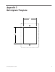
Switchplate Template Appendix C Switchplate Template 1.85" 2.35" 54-0195 Rev.
EchoStar IRD Activation Procedure Appendix D EchoStar IRD Activation Procedure If you have purchased a DISH Network system, there is a chance that your EchoStar IRD will fail to acquire the satellite when you first activate it. This has been known to happen in IRDs that have not been activated within several months of their manufacture.
A Guide to TracVision L2 10. Type in the elevation that you obtained in Step 6. - Type EL,xxx (e.g., Elevation of 30.2° = EL,302) 11. Using a compass, take a bearing on an object that is approximately on the azimuth obtained in Step 6. 12. Type in an azimuth that points the antenna in the direction of the object selected in Step 11. - Type AZ,xxxx (e.g.
Startup Data Sequences Appendix E Startup Data Sequences The data on the following pages presents the startup data sequences registered by the TracVision L2. The first section shows the sequences registered by a system that is connected to an IRD low-speed data port. The second section shows the sequences registered by a system that is NOT connected to an IRD low-speed data port. Both sections show two routines.
A Guide to TracVision L2 *** Entering Tracking *** +POS: 61.8 36.5 1260 +POS: 62.2 36.3 1346 +POS: 64.0 36.5 1716 *** Entering Satellite Check *** +POS: 64.3 --------Confirming proper satellite lock 36.1 1747 Satellite Located IRD Signal Quality = 54 +POS: 66.1 35.6 1522 +POS: 64.6 35.5 1749 IRD Signal Quality = 58 +POS: 66.2 36.1 1467 +POS: 64.5 35.8 1757 “Instant On” Startup Sequence ?PGM KVH TracVision L2 Rev X - Version X.
Startup Data Sequences E.2 System Not Connected to IRD Data Standard Startup Sequence ?PGM KVH TracVision L2 Rev X - Version X.
A Guide to TracVision L2 +POS: 331.7 33.4 2153 Switch held: wrong satellite--------------SAT SELECT switch pressed Exclude: No longer search AZ = 331.7, EL = 33.4 *** Entering Search Mode 1 *** -----------Searching for a different satellite Search1 decided to go to: AZ = 335.9, EL = +POS: 23.5 +POS: 162.5 33.5 33.5 518 33.5 1105 *** Entering Search Mode 2 *** +POS: 150.5 +POS: 80.1 +POS: 180.0 33.4 1108 33.4 889 34.0 1092 *** Entering Search Mode 3 *** +POS: 180.0 34.3 873 +POS: 22.
Startup Data Sequences VEL_INDEX: Az = 1996, El = 2182 ----------Expected range is 1700-2300 RATE BIAS: PASS --------------------------Az & El values above are within valid ranges *** Initializing Finetune *** +POS: 360.0 23.1 1575 Signal Peaked: AZ = 0.00, EL = 22.50, RF = 1919 *** Tracking Satellite *** +POS: 360.0 22.5 1917 +POS: 360.0 22.5 1976 Switch held: wrong satellite--------------SAT SELECT switch pressed Exclude: No longer search AZ = 0.0, EL = 22.
Maintenance Port Parser Commands Appendix F Maintenance Port Parser Commands TracVision L2 system parser commands are parsed when the system receives an ASCII carriage return (Hex 0D). An ASCII line feed (Hex 0A) is permitted but is ignored in any transmitted command. All system responses are terminated with an ASCII carriage return followed by a line feed and ending with either an acknowledge character (ASCII > (Hex 3E)) or a not-acknowledge character (ASCII ? (Hex 3F)).
A Guide to TracVision L2 F.2 Manual Positioning Commands To execute the following commands, first put the antenna unit in idle mode by typing HALT and pressing “ENTER.” Positioning commands may be entered after the antenna comes to rest.
Maintenance Port Parser Commands Azimuth CCW Step Function: commands a 0.1 deg CCW manual step in azimuth angle Command: 4 Argument: none Response: echoes the command Elevation UP Step Function: commands a 0.1 deg UP manual step in elevation angle Command: 8 Argument: none Response: echoes the command Elevation DOWN Step Function: commands a 0.1 deg DOWN manual step in elevation angle Command: 2 Argument: none Response: echoes the command F.
A Guide to TracVision L2 F.
KVH Industries Limited Warranty TracVision L2 Limited Warranty on Hardware KVH Industries, Inc. warrants the KVH product purchased against defects in materials for a period of TWO (2) years and against factory labor costs for a period of ONE (1) year from the date of original retail purchase by the original purchaser.
KVH Industries, Inc. 50 Enterprise Center • Middletown, RI 02842 • U.S.A. Phone: +1 401 847-3327 • Fax: +1 401 849-0045 • E-mail: info@kvh.com • Internet: www.kvh.com KVH® and TracVision® are registered trademarks of KVH Industries, Inc. TVL2_OM_Cover_10.