
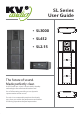
Manual


Cooling
The SL3000 Amplier have a comprehensive cooling system featuring chassis sealed PCB board mounting and shock
mounted, speed controlled fans. This means that the cooling system never drives air across PCB boards, connectors or
components, ensuring prolonged electronic component lifespan and minimizing maintenance cycles.
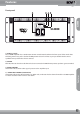
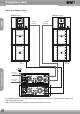
Air is drawn into the front of the amplifer by the two fans on the rear panel, this passes over the cooling fans of the heat
sinks and exhausts through the rear. If the heat sink gets too hot, its sensing circuit will open the output relay, discon-
necting the load.
It is important to have an adequate air supply at the front of the amplier, and enough space around the rear of the
amplier to allow the cooling air to escape. If the unit is rack mounted, do not use doors or covers on the rear of the rack,
the exhaust air must ow without restriction. If you are using racks with closed backs, use fans on the rear
rack panel to ensure an ample air supply.
NOTE: The lters at the top and bottom of the front panel must be kept clean and free of dust and dirt to allow full
operation-CHECK PERIODICALLY
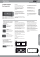
AC Requirements
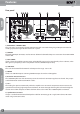
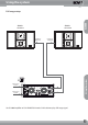
Two PowerCon cables are provided to connect the SL3000 Amplier to a suitable AC power supplies. Each cable powers
each separate amplier channel for sucient current delivery.
The PowerCon is a connector without breaking capacity, i.e. the PowerCon should not be connected or disconnected
under load or while it is live. Always isolate your AC supply before disconnecting the PowerCon connector.
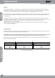
Your amplier will be supplied preset to the voltage used in your area. The table below provides typical current draw
gures for the SL3000 Amplier.
Current draw of SL3000 Amplier
Getting started
AC Input Current draw with amplier running at
Average Power (Each Channel)
Current draw with amplier running at
Peak Power (Each Channel)
250V 3.2A 5A
230V 3.5A 5.4A
115V 7A 11A
SL3000
Getting started
6