ESP4000 User Guide The future of sound. Made perfectly clear. At KV2 Audio our vision is to constantly develop technologies that eliminate distortion and loss of information providing a true dynamic representation of the source. Our aim is to create audio products that absorb you, place you within the performance and deliver a listening experience beyond expectation.
Contents Warranty Your ESP4000 is covered against defects in material and workmanship. Refer to your supplier for more details. Service In the unlikely event that your ESP4000 develops a problem, it must be returned to an authorised distributor, service centre or shipped directly to our factory. Because of the complexity of the design and the risk of electrical shock, all repairs must be attempted only by qualified technical personnel.
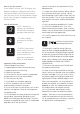
How to use this manual As you read this manual, you’ll find figures and diagrams to help you understand and visualise what you’re reading. You’ll also find numerous icons that serve as cues to flag important information or warn you against improper or potentially harmful activities. Icons Used Include “NOTE” identifies an important or useful piece of information relating to NOTE the topic under discussion. TIP “TIP” offers a helpful tip relevant to the topic at hand.
Introducing the ESP4000 The ESP4000 is a four channel rack mountable power amplifier. The unit contains four seperate 1000 watt amplifiers, two independent power supplies (two channels running off each power supply) signal paths, inputs and outputs as well as limiting and low frequency enhancement on each of the four channels within a four rack unit chassis. It can be used to power a range of passive loudspeakers as well as being specifically designed for optimised performance with KV2 Audio’s ESD Series.
Rack Mounting ESP4000’s will mount in standard 19” rack systems. Integral rear mounting rack ears are also provided for additional support. It is important that you do not rely on fixing and mounting the ESP4000 using just the front panel as support. Use eight screws and washers to mount the amplifier to the equipment rack rails (four for the fronts and four for the rear). We recommend using a shock mounted rack for touring use to prolong the life of your ESP4000.
It is recommended that the voltage supply be within the rated NOTE voltage window. This ensures that AC voltage variations from the service entry or peak voltage drops due to cable runs - do not cause the amplifier to cycle on and off or cause damage to the power supply. NOTE: NOTE: For best performance, the AC cable voltage drop should not exceed 10 volts, or 10 percent at 115 volts and 5 percent at 230 volts.
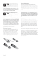
The burst current is the maximum rms current during a period of approximately one second, used to select the rating of most magnetic breakers and to calculate the peak voltage drop in long AC cables according to the formula: V pk (drop)= I pk x R (cable total) The ultimate short-term peak current is used to select the rating of fast reacting magnetic breakers. Use the table below as a guide when selecting cable gauge size and circuit breaker ratings for your operating voltage.
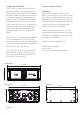
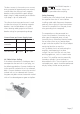
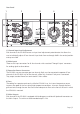
Chapter 3: Features Front Panel 1 2 3 4 5 1) AC Mains Switch The ESP4000 has combination AC mains switch/circuit breakers on the front panel. If either of the switches shuts off during normal use, push it back to the ON position once. If it will not stay on you should take the unit to qualified service personnel to have it serviced.
Rear Panel 1 2 3 4 1 -6dB 1 5 0dB min. 2 250 VAC -6dB 2 230 VAC 0dB 2 115 VAC min. 2 -6dB 3 3 0dB min. 2 SERIAL NUMBER -6dB 4 4 0dB WWW.KV2AUDIO.COM DESIGNED BY KV2 AUDIO MANUFACTURED IN THE EUROPEAN UNION min. 2 1) Channel Input Level Adjustment Each channel of the ESP4000 features an Input Level adjustement potentiometer that allows the user to individually adjust all four channel’s input levels from oo through -6dB in the vertical position and up to to 0dB.
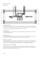
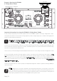
4ohm 1800W Chapter 4: Running the ESP4000 in “Bridge Mono” Mode PHASE REVERSE CABLE + SIGNAL INPUT 1 -6dB 1 0dB min. 2 250 VAC -6dB 2 230 VAC 2 115 VAC 0dB min. 2 -6dB 3 3 0dB min. 2 SERIAL NUMBER -6dB 4 4 0dB WWW.KV2AUDIO.COM DESIGNED BY KV2 AUDIO MANUFACTURED IN THE EUROPEAN UNION min. 2 Input level potentiometers of each bridged channel must be set to the same level. Channels 3 and 4 can also be used in the same way to achieve the same ends.
System Acoustic Perfomance -1dB Response Channel Crosstalk Signal to Noise Ratio Total Harmonic Distortion 3Hz ÷ 40kHz >60dB >115dB <0.005% (1W) / <0.01% (clip -1dB) Output Channels Amplifier Type Number of Channels Total Output Power Max. Output Voltage Max. Output Current Minimum load impedance per channel Out. Power 16Ω - 1 channel / 2 channels loaded Out. Power 8Ω - 1 channel / 2 channels loaded Out. Power 4Ω - 1 channel / 2 channels loaded Out. Power 2Ω - 1 channel / 2 channels loaded Out.
The future of sound. Made perfectly clear. At KV2 Audio our vision is to constantly develop technologies that eliminate distortion and loss of information providing a true dynamic representation of the source. Our aim is to create audio products that absorb you, place you within the performance and deliver a listening experience beyond expectation. KV2 Audio, Nádražní 936, 399 01 Milevsko, Czech Republic T +44(0)1423 816868 F +44(0)1423 816869 www.kv2audio.