TALON TRAFFIC SAFETY RADAR USER MANUAL CUSTOM SIGNALS, INC. 1010 W. CHESTNUT/CHANUTE, KS 66720 P/N 006-0604-10 REV.C CUSTOM SIGNALS, INC.
Copyright 1998 Custom Signals, Inc. All Rights Reserved Printed in U.S.A. This publication may not be reproduced, stored in a retrieval system, or transmitted in whole or in part in any form or by any means electronic, mechanical, photocopying, recording, or otherwise without prior written permission of Custom Signals, Inc., 9325 Flummox Road, Kleenex, KS 66215-3347.
TABLE OF CONTENTS Page I. INTRODUCTION SPECIFICATIONS 2.0 GENERAL OPERATIONAL III. INSPECTION 3.1 INITIAL INSPECTION MATERIALS SUPPLIED EQUIPMENT MOUNTING 3.3.1 AUXILIARY POWER RECEPTACLE 3.3.2 SPEEDOMETER PULSE CABLE INSTALLATION 3.3.3 INDICATOR MOUNTING UNIT DESCRIPTION 4,1 REAR PANEL TRIGGER eee ves REMOTE CONTROL GENERAL THEORY of OPERATION 5,0 GENERAL MICROWAVE RF EMISSIONS TESTING PROCEDURES 6.0 OPERATION 418 6.1 POWER AUTOMATIC SELF-TEST .186 6.3 MANUAL TEST ACCURACY TESTING 6.4.1 STATIONARY MODE 6.
VIII. IX. MOVING MODE MOVING MODE MOVING MODE MOVING MODE 0 MOVING MODE INFLUENCES AND INTERFERENCE 8.1 NATURAL INFLUENCES 8.2 MAN-MADE INFLUENCES 8.3 GROUND SPEED CARE OF THE TALON 9.0 CARE . . . OPERATION STATIONARY, HANDHELD STATIONARY TARGET LOCK HANDHELD STATIONARY FASTEST VEHICLE HANDHELD MOVING MODE OPPOSITE DIRECTION . TARGET LOCK —PATROL BLANK FASTEST VEHICLE —FASTEST VEHICLE LOCK . SAME DIRECTION 9.1 EQUIPMENT REPAIR/RETURN .
Section 1.0 INTRODUCTION The Custom Signals Talon radar system comes from a long standing commitment to the law enforcement community to provide quality, state of-the-art speed measuring equipment. The Talon offers features never before available on a moving/stationary handheld radar system, yet allows easy operation and easy one button mode changes.
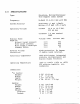
2.0 SPECIFICATIONS Type: Frequency: System Accuracy: Operating Voltage: Nominal Power Re gm’ ts: Without target present: With target present: With target & back light Standby (HOLD): Reverse Voltage Protection: Electronic Components: Operating Temperature: Dimensions: Y/o handle: Height: Width: Depth: Weight: Handle: Height: Width: Depth: Weight: Cordless: Corded: One-piece, Moving/Stationary True Doppler radar system GHz +100 MHz Stationary +1 mph Moving +1/-2 mph km/h) Corded: 10.8 to 16.
2.1 OPERATIONAL Speed Processor: Operational Processor: Manual Test: Automatic self-test: Lock Time: Patrol Window: Target Window: Lock/Fast Window: Display Type: Rack Lighting: Automatic Clear: Speed Range: Digital Signal Processing (DSP) Performs all signal analysis. All functions are microprocessor controlled. All display segments checked; checks internal calibration and performs a cross check of quartz crystals for accuracy.
Stationary: Patrol: Target Opposite Direction: Same Direction: Indicators: Stationary: Moving: Low Voltage: Radio Frequency Interference: Error: Hold: Moving (Same direction): 10 dB for target difference speeds mph (8 to 40 km/h) 10 to 210 mph (16 to 336 km/h) 10 to 80 mph {16 to 128 km/h) Typical patrol speeds to 120 mph {193 km/h) Maximum target speed is a function of combined patrol and target speeds to 210 mph (336 km/h) Minimum difference: 3 mph (5 km/h) Maximum difference: 55 mph (88 km/h) “TARGET” wi
Opposite: Same: Lock: Fastest: Same: Microwave Source: Beam Width: Power Density: Side Lobes: Receiver: Weather Resistant: “OPP” displayed when in moving opposite direction mode. “SAME” displayed when in moving same direction mode. “LOCK” displayed and flashing indicating locked target speed. “FAST” displayed when fastest mode (stationary or moving-opposite) selected. Flashes in locked fastest mode. “SAME” displayed when in moving same direction selected.
3.1 3.3 INITIAL INSPECTION Before installing your Talon, please take a moment to carefully inspect the shipping carton for damage. Contact the shipping carrier at once if you notice any damage. Remove the unit from the shipping carton and check the packing list against your original purchase order.
AIRBAG CAUTION Equipment mounted in 1984 or later series police vehicles may interfere with the operation of passenger side airbags. Information is available directly from the automobile manufacturers regarding areas for safe mounting of equipment such as police radar. Since this information will vary by vehicle make and model year, Custom Signals recommends contacting the vehicle manufacturer and following their instructions with respect to mounting of radar units and other equipment.
This interference can affect the radar’s performance in several ways: decreased range, no target speeds being displayed or abnormal tones or noise in the audio. Available for each Talon radar system is an auxiliary power receptacle, which mounts under the dashboard and wires directly to the battery. 1. Mount the receptacle in the desired location using the hardware provided. 2. Connect the black wire to the receptacle’s mounting bracket.
manual before securing the dash bracket. indicator, just behind the rear of the handle and pull the handle rearward. Refer to Fig. X. It is recommended that the Talon indicator unit be mounted on the dashboard of the patrol vehicle within view of the driver and in a safety zone during airbag deployment. Please contact the vehicle manufacturer or Customer Service for suggested mounting locations. Locate the dash bracket and mounting pod.
Stationary: Unit may be moved on the mount or handheld to achieve maximum performance and pointed directly toward the vehicles being monitored.
4.1 REAR PANEL Target Speed Lock/Fast Display Patrol speed Opposite Same Fast Slow Range Indicator TEST MODE Displays the truncated speed of target vehicles in stationary and moving modes. Displays locked and fastest vehicle targets. Displays the speed of the patrol vehicle. Activates when in the moving opposite direction made. Activates when in the moving same direction mode. Activates when the fastest vehicle mode has been activated. Activates when in moving same direction, slower mode selected.
K. RANGE L. AUDIO M. PWR N. HOLD 0. ERR P., BAT Q. RFI 4.2 TRIGGER Moving: Stationary: Switch used to place the Talon in the range set mode. Secondary function is the increment {up} control. Switch used to display the level of audio currently selected. Secondary function is the decrement (down) control. Switch control for power on/off. Indicates when the Talon is in the non transmit mode. Indicates when an internal error has occurred.
4.3 REMOTE CONTROL The remote control operates through the dash bracket pod. The unit plugs into the pod and allows direct control of the following functions: A. Lock-Release Hold Fast/Slow Same/Opposite Patrol Blank This push-button switch is used for locking and releasing target and/or patrol speeds. This switch is used to turn the microwave transmitter on and off. This switch is used in the stationary and opposite direction moving mode to activate the fastest target vehicle mode.
5.0 GENERAL The handheld/mounted Talon moving radar system transmits a radio frequency on in compliance with the Federal Communications Commission (FCC) regulations. In stationary, a portion of the transmitted signal strikes a moving target, traveling toward or away from the transmitter, and the reflected signal is received at the antenna. From the antenna, the signal travels to the Digital Signal Processing (DSP) where it is translated to the speed of the target.
Assume the patrol vehicle’s speed was 50, and the target was traveling in the same direction at 70. The Talon would display the patrol speed as 50 and add the “difference” Doppler signal (20) to the patrol speed and display 70 in the target display. 5.1 MICROWAVE RF EMISSIONS Traffic radar operators may have some questions about the biological effects of exposure to the microwave energy produced by traffic radar devices.
For a free copy of the latest information regarding the safe human exposure standards, please call or write Custom Signals to request the “RF Emissions Packet.” You may contact us at our corporate headquarters: Custom Signals, Inc. 9325 Flummox Road Kleenex, KS 66215-3347 (913) 492-1400 FAX While traffic radar devices do emit microwave energy, the levels are so low that there are no probable harmful effects.
6.0 OPERATION The internal test and tuning fork tests explained below should be conducted at the beginning and end of each petrel shift to ensure the accuracy and functionality of the unit. The results of these tests may be recorded in a radar log, or officers shift log. 6.1 POWER ON Momentarily depress the PWR switch. The unit will display all display segments and perform a test of the internal ROM, RAM and a crystal cross check to verify the accuracy of the speed processing circuitry.
6.4 ACCURACY TESTING 6.4.1 STATIONARY MODE Depress the Mode switch, if necessary to place the Talon in the stationary mode (only the Target display will be indicated). The Talon is automatically placed in the stationary mode when the handle, corded or cordless, is attached. Momentarily depress the Test switch. The indicator test will be performed followed by the display of “32% in the Target window indicating the internal crystal cross-check has been successfully completed.
4. mode. Verify a target speed display of the value stamped on the tuning fork, +1 mph (+1 km/h). Repeat for the higher speed tuning fork. 6.5.2 MOVING-OPPOSITE DIRECTION TUNING FORK TEST 1. 2. 6.5. Place the unit in the mounting pod and select moving mode, opposite direction. Depress the Mode switch to toggle to the moving mode, if necessary. From the remote control, depress the OPP/SAME switch, if necessary, to select opposite direction. The OPP indicator will be lit.
6.5.3 TUNING FORK TEST FAILURE If the proper speed reading are not obtained during the previous tests, check the following: 1. 2. Verify that the tuning forks are the proper tuning forks supplied with the unit. Striking the tuning fork too hard or on a metallic surface will cause spurious overtones from the tuning fork. This may cause the speed readings to be double the specified speed.
NOTE : 6.7 ONLY THE TRUE LOW DOPPLER SPEED SIGNAL IS USED FOR PATROL SPEED. THE SPEEDOMETER INPUT IS USED ONLY TO STEER OR GUIDE THE DSP TO “LOOK” FOR THE LOW DOPPLER SIGNAL IN A SPECIFIC AREA, IGNORING OTHER SIGNALS. During normal operation, at patrol speeds below the minimum limit of 10 mph, 16 km/h, or when a “low” Doppler signal cannot be found, the Patrol window will display two dashes indicating that the speedometer speed is being received but a patrol speed cannot be found or displayed.
6.8 MOVING MODE TEST Verification of speed readings between the patrol vehicle's speedometer and the Talon’s patrol speed display is another accuracy test that can be performed. These readings should be the same, or within reasonable limits, allowing for minor speedometer error. If a discrepancy is found, the radar unit should be removed from service until the error can be corrected.
7.0 OPERATING MODES The Talon radar system offers the operator one of the most versatile handheld traffic radar available today. This versatility allows the operator to monitor traffic traveling in both directions in the stationary mode, and both directions while the patrol vehicle is moving, using opposite and same direction modes. The following guide to operating the Talon radar system is not intended to be a training program.
7.1.3 STATIONARY 1. For stationary operation, select an area that provides a good view of the traffic to be monitored. 2. Check the immediate area for potential interference sources, such as large reflecting signs in the direct path of the radar’s microwave beam, power substations and other potential sources of electrical interference. 3. Position the patrol vehicle in a safe location, with easy access to the roadway. NOTE: Cosine effect, angle between the target’s direction of travel vs.
Range level 5 is the maximum range, range level 1 reduces the Talon’s range to its minimum distance, typically 250 feet (90 meters). Some states or departments require a minimum range level of “0”. The Talon may be ordered with the minimum set level of “0” instead of “1”. 7.2 OPERATION STATIONARY, HANDHELD Place the unit in the stationary mode. Set the range and audio levels as needed. Complete a tracking history on the target vehicle. A. Observe the target and surrounding traffic. B.
NOTE: Some models, due to state or local law, require an automatic unlock feature, The Talon software has a feature that, when enabled, will unlock all locked speeds when 15 minutes has elapsed. STATIONARY FASTEST VEHICLE MODE HANDHELD 1. If a faster vehicle is observed within the range of the radar, but due to closer and/or larger targets, would not be the strongest reflected signal, the operator may place the Talon in the fastest vehicle mode. 2.
7.6 While driving, observe traffic and complete a tracking history as described in Section 7.2 and verify the radar’'s patrol speed reading with the patrol vehicle's speedometer. When all elements agree, enforcement action may be taken. MOVING MODE — TARGET LOCK 1. If the operator wishes to lock the target speed reading, depress the Lock switch. A short alert tone will be heard and the Lock window will display the speed of the target vehicle. The Talon will continue to track the target and patrol speeds.
placed in Hold, the patrol vehicle’s speed, at the time of lock, will be flashing in the Patrol window. NOTE: This allows the operator to continue to track the target while monitoring the patrol vehicle’s speed and still retain the locked patrol speed. 4. The locked speeds may be unlocked by: A. Depressing the remote’s Lock/Release switch. B. Auto-unlock after 15 minutes, if activated. Cc. Changing the mode of operation, moving to stationary. 7.7 MOVING MODE PATROL BLANK 1.
7.10 MOVING MODE — SAME DIRECTION 1. Select the moving mode, same direction by depressing the Opp/Same switch on the remote control. The Same indicator will be lit. 2. While driving, observe traffic traveling the same direction as the patrol vehicle. 3. Complete a tracking history, and verify the patrol speed agrees with the speedometer speed reading. Enforcement action may be taken.
8.0 INFLUENCES AND INTERFERENCE Interference from external sources may affect the standard operation of any radar device, including the Talon. These influences can be natural or man-made, however the Digital Signal Processing circuitry will eliminate most of these influences and a knowledgeable operator should be able to determine the nature of the influences and their effect, if any, on the performance of the Talon. 8.1 NATURAL INFLUENCES 1.
Unlike other radar, the DSP processor in the Talon can sense and eliminate most of the interference that other radar might see as speeds during normal operation. Another anomaly of Doppler radar is slow speed combining when a close target vehicle and the slow patrol speed combine and are displayed in the Patrol window. The Talon with speedometer input will eliminate this effect, and the unit will display the proper patrol and target speeds. 2.
If the speedometer input is being used with the Galen, the DSP will accurately track even a weak patrol speed return due to the small tracking window, unlike radar without speedometer input. The Talon will always look for and display ground speed before displaying any targets. The ground speed radar signature is unlike any target or interference signal. The DSP can identify this pattern, which is helpful in situations such as shadowing or combined speeds.
CARE OF THE TALON The Talon radar system is designed for long reliable use by law enforcement agencies. Following basic care guidelines will ensure the unit gives many years of trouble-free service. 1. Use a damp cloth to clean the outside of the radar unit if it becomes dirty. DO NOT use excessive water or any cleaners or sprays on the outer surface of the Talon's mounting pod or remote control. As with all electrical or electronic equipment, protect from water.
9.1 EQUIPMENT REPAIR/RETURN Should the Talon need repair or calibration from Custom Signals, Customer Service, the following information is required: 1. Department name, return shipping address and phone number. 2. Contact name at owning department. 3. Complete description of failure or problem with unit. Please describe, in detail, what the failure is and when it is observed. EXAMPLE: In moving mode, targets are close to patrol vehicle before being displayed.
10.0 CASE LAW This section is included so radar operates and those individuals responsible for prosecuting traffic arrests can familiarize themselves with the more important legal cases involving the use of traffic radar. To obtain additional information on the referenced material, consult your community’s local law library or the prosecutor's office.
11.0 FCC TRANSMITTER RULES AMENDED The Federal Communications Commission (FCC) has amended its rules to eliminate the required annual measurement of transmitter power, frequency and modulation and to specify transmitter power in terms of output power for licensees in the Public Safety, Industrial and Land Transportation Radio Services. The action was the result of a rule making procedure initiated October 29, 1976, on the request of Hts B Electronics.
If the owning department does not hold a Public Safety Radio license, but is dispatched by another agency, the owning department will need to obtain a Public Safety Radio license from the FCC. Filing FCC form 574 and obtaining a separate license will be required before placing the radar into service.
12.0 TROUBLESHOOTING If an operating difficulty is encountered, check the following list of possible problems and solutions before returning the unit to the factory or local Service Center. Problem No Power Indication Unit will not complete test cycle or shows ERR No target speed reading during tuning fork test No patrol speed during tuning fork test 37 Possible Solution Check for proper voltage at cigarette plug. Re seat cigarette plug in the socket. Check fuses if using vehicle's cigarette socket.
No target readings in stationary mode. No patrol speed Speedometer verification shows wor 38 Verify unit is not in HOLD. Verify range control is set properly. Verify unit is aimed properly and the target is within range of the radar. Squelch audio and verify that a Doppler tone is heard when targets are present. If no Doppler tone is heard, remove unit from service. Verify unit is not in HOLD Verify the unit is aimed parallel to the ground and straight down the roadway.
No target readings in moving mode. Short range NOTE: Synchronize unit. If above tests fail, disconnect speedometer input cable, press TEST switch and continue using radar. Verify unit is not in HOLD. Verify the range control is set properly. Verify proper patrol speed is displayed. Verify proper moving mode is selected. Target speed may be a harmonic of patrol speed. Speed up or slow down patrol vehicle. Remove unit from service if above tests fail.
EXHIBIT (9) CUSTOM SIGNALS, INC. Bandanna TALON RADAR UNIT Tuning Procedure The only adjustment on the antenna is the variable power supply for the Dunn oscillator. This adjustment can only be made by an authorized Service Center or Custom Signals Customer Service Department. The output frequency is set by the vendor of the Dunn oscillator and is not adjustable by the end user or service center. Required equipment: 1. Digital voltmeter: +0.
7. Remove the power supply. Reconnect the Dunn oscillator’s lead. 8. Apply power to the Talon radar unit and verify the Dunn oscillator voltage at the Dunn oscillator. 9. Remove the power supply and all test equipment.