
User Guide

FXAlg #734: Distort + Rotary
Algorithm Reference-111
FXAlg #734: Distort + Rotary
Small distortion followed by rotary speaker effect
Allocation Units: 2
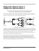
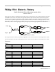
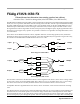
Distort + Rotary models an amplifier distortion followed by a rotating speaker. The rotating speaker has separately
controllable tweeter and woofer drivers. The algorithm has three main sections. First, the input stereo signal is
summed to mono and may be distorted by a tube amplifier simulation. The signal is then passed into the rotator
section where it is split into high and low frequency bands and the two bands are run through separate rotators.
The two bands are recombined and measured at two positions, spaced by a controllable relative angle (microphone
simulation) to obtain a stereo signal again. Finally the signal is passed through a speaker cabinet simulation.
Block diagram of Distort + Rotary
The first part of Distort + Rotary is a distortion algorithm. See the section of this book on FXAlg #723 for details.
Next the signal passes through a rotating speaker routine. See the section of this book on FXAlg #733 for details.
Parameters:
PAGE 1
PAGE 2
PAGE 3
In/Out In or Out Out Gain Off, -79.0 to 24.0 dB
Cabinet HP 16 to 25088 Hz Dist Drive 0 to 96 dB
Cabinet LP 16 to 25088 Hz DistWarmth 16 to 25088 Hz
Xover 16 to 25088 Hz Mic Angle 0.0 to 360.0 deg
Lo Gain Off, -79.0 to 24.0 dB Hi Gain Off, -79.0 to 24.0 dB
Lo Rate -10.00 to 10.00 Hz Hi Rate -10.00 to 10.00 Hz
Lo Size 0 to 250 mm Hi Size 0 to 250 mm
Lo Trem 0 to 100% Hi Trem 0 to 100%
ResH/LPhs 0.0 to 360.0 deg
LoResonate 0 to 100% HiResonate 0 to 100%
Lo Res Dly 10 to 2550 samp Hi Res Dly 10 to 2550 samp
LoResXcurs 0 to 510 samp HiResXcurs 0 to 510 samp
Distortion
Rotator
Rotator
L Input
R Input
L Output
R Output
Out GainCabinet