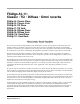
Algorithm Reference ©1998 All rights reserved. Kurzweil is a product line of Young Chang Co.; V. A. S. T. is a registered trademark, and Kurzweil, K2500, and KDFX are trademarks of Young Chang Co. Hammond and Leslie are trademarks of Hammond Suzuki USA. SRS is a trademark of SRS Labs, Inc. All other products and brand names are trademarks or registered trademarks of their respective companies. Product features and speciÞcations are subject to change without notice. Part Number: 910319 Rev.
FXAlg #1: MiniVerb ¥ FXAlg #2: Dual MiniVerb FXAlg #1: MiniVerb ¥ FXAlg #2: Dual MiniVerb Versatile, small stereo and dual mono reverbs Allocation Units: 1 for MiniVerb, 2 for Dual MiniVerb MiniVerb is a versatile stereo reverb which is found in many combination algorithms, but is equally useful on its own because of its small size. The main control for this effect is the Room Type parameter. Room Type changes the structure of the algorithm to simulate many carefully crafted room types and sizes.
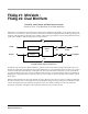
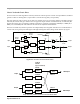
FXAlg #1: MiniVerb ¥ FXAlg #2: Dual MiniVerb Pan Dry L Output L Input MiniVerb Wet Balance R Input MiniVerb Wet Balance R Output Dry Pan Simplified block diagram of Dual MiniVerb Dual MiniVerb has a full MiniVerb, including Wet/Dry, Pre Delay and Out Gain controls, dedicated to each of the left and right channels. The two blocks in the diagram above labeled ÒMiniVerbÓ contain a complete copy of the MiniVerb on the previous page.
FXAlg #1: MiniVerb ¥ FXAlg #2: Dual MiniVerb Parameters (Dual MiniVerb): PAGE 1 L Wet/Dry 0 to 100%wet R Wet/Dry 0 to 100%wet L Out Gain Off, -79.0 to 24.0 dB R Out Gain Off, -79.0 to 24.0 dB L Wet Bal -100 to 100% R Wet Bal -100 to 100% L Dry Pan -100 to 100% R Dry Pan -100 to 100% PAGE 2 L RoomType Hall1 L RvrbTime 0.5 to 30.0 s, Inf L Diff Scl 0.00 to 2.00x L Density 0.00 to 4.00x L Size Scl 0.00 to 4.
FXAlg #1: MiniVerb ¥ FXAlg #2: Dual MiniVerb Size Scale A multiplier which changes the size of the current room. At 1.00x, the room will be the normal, carefully-tweaked size of the current Room Type. Altering this parameter will change the size of the room, and thus will cause a subtle coloration of the reverb (since the roomÕs dimensions are changing). Density A multiplier which affects the density of the reverb. At 1.
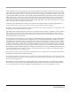
FXAlg #3: Gated MiniVerb FXAlg #3: Gated MiniVerb A reverb and gate in series Allocation Units: 2 This algorithm is a small reverb followed by a gate. The main control for the reverb is the Room Type parameter. Room Type changes the structure of the algorithm to simulate many carefully crafted room types and sizes. Spaces characterized as booths, small rooms, chambers, halls and large spaces can be selected. See the previous section (FXAlg #1-2) for details on the reverb.
FXAlg #3: Gated MiniVerb Parameters: PAGE 1 Wet/Dry 0 to 100%wet Out Gain Off, -79.0 to 24.0 dB Rvrb Time 0.5 to 30.0s, Inf HF Damping 16 to 25088 Hz L Pre Dly 0 to 620ms R Pre Dly 0 to 620 ms Hall1 Diff Scale 0.00 to 2.00x Size Scale 0.00 to 4.00x Density 0.00 to 4.00x PAGE 2 Room Type PAGE 3 Gate Thres -79.0 to 0.0 dB Gate Time 0 to 3000 ms Gate Duck In or Out Gate Atk 0.0 to 228.0 ms Gate Rel 0 to 3000 ms GateSigDly 0.0 to 25.
FXAlgs #4-11: Classic ¥ TQ ¥ Diffuse ¥ Omni reverbs FXAlgs #4-11: Classic ¥ TQ ¥ Diffuse ¥ Omni reverbs FXAlg #4: Classic Place FXAlg #5: Classic Verb FXAlg #6: TQ Place FXAlg #7: TQ Verb FXAlg #8: Diffuse Place FXAlg #9: Diffuse Verb FXAlg #10: OmniPlace FXAlg #11: OmniVerb More Complex Reverb algorithms Allocation Units: ÒClassicÓ 2; others 3 This set of 2 and 3 PAU sized algorithms can be divided into 2 groups: Verb and Place. Verb effects allow user friendly control over medium to large spaces.
FXAlgs #4-11: Classic ¥ TQ ¥ Diffuse ¥ Omni reverbs Some algorithms use injector mechanisms when feeding a signal into the ambience generator. An injector creates copies of the input signal at different delay intervals and feeds each copy into the ambience generator at different points. This results in finer control over the onset of the reverb. By tapering the amplitudes of early copies vs. late copies, the initial build of the reverb can be controlled. Inj Build controls this taper.
FXAlgs #4-11: Classic ¥ TQ ¥ Diffuse ¥ Omni reverbs Classic Verb and Classic Place: Classic reverbs are 2-PAU algorithms with early reflections. The late portion consists of an input diffuser; ambience generator with low shelving filters, lowpass filters, and LFO moving delays; and predelay.
FXAlgs #4-11: Classic ¥ TQ ¥ Diffuse ¥ Omni reverbs PAGE 1 (Classic Verb) Wet/Dry -100 to 100% Out Gain Off; -79.0 to 24.0 dB Rvrb Time 0.00 to 60.00 s EarRef Lvl -100 to 100% HF Damping 0 to 25088 Hz Late Lvl -100 to 100% L Pre Dly 0.0 to 230.0 ms R Pre Dly 0.0 to 230.0 ms PAGE 1 (Classic Place) Wet/Dry -100 to 100% Out Gain Off; -79.0 to 24.0 dB Absorption 0 to 100% EarRef Lvl -100 to 100% HF Damping 0 to 25088 Hz Late Lvl -100 to 100% L Pre Dly 0.0 to 230.0 ms R Pre Dly 0.
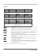
FXAlgs #4-11: Classic ¥ TQ ¥ Diffuse ¥ Omni reverbs TQ Verb and TQ Place: TQ reverbs are 3-PAU algorithms with early reflections. The late portion consists of an input diffuser, injector, ambience generator with a lowpass filter, low shelving filter, and LFO moving delays, and predelay. The early reflection portion combines a combination of delays, diffusers, and feedback. The relative delay lengths are all fixed but are scalable with the E Dly Scl parameter.
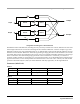
FXAlgs #4-11: Classic ¥ TQ ¥ Diffuse ¥ Omni reverbs E Dly Scl (Applies to All Delays) L Input E PreDly L E Fdbk Amt Delay Diffusor Delay Diffusor Delay Diffusor L ER Output E Build Delay Delay R Input E PreDly R E Build Delay Diffusor Delay Diffusor Delay Diffusor R ER Output Early reflection portion of TQ Verb and TQ Place PAGE 1 (TQ Verb) Wet/Dry -100 to 100% Out Gain Off; -79.0 to 24.0 dB Rvrb Time 0.00 to 60.
FXAlgs #4-11: Classic ¥ TQ ¥ Diffuse ¥ Omni reverbs PAGE 2 (TQ Place) Room Type Booth1, ... TrebShlf F 16 to 25088 Hz Size Scale 0.00 to 2.50x TrebShlf G -79.0 to 24.0 dB DiffAmtScl 0.00 to 2.00 x DiffLenScl 0.00 to 2.50 x LF Split 16 to 25088 Hz LFO Rate 0.01 to 10.00 Hz LF Time 0.50 to 1.50 x LFO Depth 0.0 to 100.0 ct Inj Build -100 to 100% Inj LP 16 to 25088 Hz Inj Spread 0.00 to 2.50 x E DiffAmt -100 to 100% E Build -100 to 100% E DfLenScl 0.00 to 2.
FXAlgs #4-11: Classic ¥ TQ ¥ Diffuse ¥ Omni reverbs Diffuse Verb and Diffuse Place: Diffuse reverbs are 3-PAU algorithms and are characterized as such because of the initial burst of diffusion inherent in the onset of the reverb. Each of these algorithms consists of an input diffuser; ambience generator with a lowpass filter, low shelving filter, and LFO moving delays; and predelay. In the Diffuse reverbs, the diffuser is implemented a little differently.
FXAlgs #4-11: Classic ¥ TQ ¥ Diffuse ¥ Omni reverbs PAGE 1 (Diffuse Verb) Wet/Dry -100 to 100% Out Gain Off; -79.0 to 24.0 dB LateRvbTim 0.00 to 60.00 s HF Damping 0 to 25088 Hz Lopass 16 to 25088 Hz L Pre Dly 0.0 to 230.0 ms R Pre Dly 0.0 to 230.0 ms Out Gain Off; -79.0 to 24.0 dB PAGE 1 (Diffuse Place) Wet/Dry -100 to 100% Absorption 0 to 100% HF Damping 0 to 25088 Hz Lopass 16 to 25088 Hz L Pre Dly 0.0 to 230.0 ms R Pre Dly 0.0 to 230.
FXAlgs #4-11: Classic ¥ TQ ¥ Diffuse ¥ Omni reverbs OmniVerb and OmniPlace: Omni reverbs are 3-PAU algorithms that consist of an input diffuser; injector; ambience generator with a lowpass filter, low shelving filter, and LFO moving delays; and predelay. The Expanse parameter adjusts the amount of reverb energy that is fed to the edges of the stereo image. A value of 0% will concentrate energy in the center of the image, while non-zero values will spread it out.
FXAlgs #4-11: Classic ¥ TQ ¥ Diffuse ¥ Omni reverbs PAGE 2 (OmniVerb) Room Type Hall1, ... Size Scale 0.00 to 2.50x InfinDecay On or Off Expanse -100 to 100% DiffAmtScl 0.00 to 2.00 x DiffLenScl 0.00 to 4.50 x LF Split 16 to 25088 Hz LFO Rate 0.01 to 10.00 Hz LF Time 0.50 to 1.50 x LFO Depth 0.0 to 100.0 ct Expanse -100 to 100% DiffAmtScl 0.00 to 2.00 x DiffLenScl 0.00 to 4.50 x PAGE 2 (OmniPlace) Room Type Booth1, ... Size Scale 0.00 to 2.
FXAlgs #4-11: Classic ¥ TQ ¥ Diffuse ¥ Omni reverbs Room Type This parameter selects the basic type of reverb being emulated, and should be the starting point when creating your own reverb presets. Due to the inherent complexity of reverb algorithms and the sheer number of variables responsible for their character, the Room Type parameter provides condensed preset collections of these variables.
FXAlgs #4-11: Classic ¥ TQ ¥ Diffuse ¥ Omni reverbs LFO Depth Adjusts the detuning depth in cents caused by a moving reverb delay line. Moving delay lines can imitate voluminous ßowing air currents and reduce unwanted artifacts like ringing and ßutter when used properly. Depth settings under 1.5ct with LFO Rate settings under 1.00Hz are recommended for modeling real spaces.
FXAlg #12: Panaural Room FXAlg #12: Panaural Room Room reverberation algorithm Allocation Units: 3 The Panaural Room reverberation is implemented using a special network arrangement of many delay lines that guarantees colorless sound. The reverberator is inherently stereo with each input injected into the ÒroomÓ at multiple locations. The signals entering the reverberator first pass through a shelving bass equalizer with a range of +/-15dB.
FXAlg #12: Panaural Room Parameters: PAGE 1 Wet/Dry 0 to 100%wet Room Size 1.0 to 16.0 m Pre Dly 0 to 500 ms HF Damping 16 to 25088 Hz Out Gain Off, -79.0 to 24.0 Decay Time 0.5 to 100.0 s Build Time 0 to 500 ms Build Env 0 to 100% PAGE 2 Bass Gain -15 to 15 dB Wet/Dry The amount of the stereo reverberator (wet) signal relative to the original input (dry) signal to be output. The dry signal is not affected by the Bass Gain control.
FXAlg #12: Panaural Room Build Env When Build Time has been set to greater than about 80ms, Build Env begins to have an audible inßuence on the early unfolding of the reverberation process. For lower-density reverberation that starts cleanly and impulsively, use a setting of 0%. For the highestdensity reverberation, and for extension of the build-up period, use a setting of 50%. For an almost reverse reverberation, set Build Env to 100%. You can think of Build Env as setting the position of a see-saw.
FXAlg #13: Stereo Hall FXAlg #13: Stereo Hall A stereo hall reverberation algorithm Allocation Units: 3 The Stereo Hall reverberation is implemented using a special arrangement of all pass networks and delay lines, which reduces coloration and increases density. The reverberator is inherently stereo with each input injected into the ÒroomÓ at multiple locations.
FXAlg #13: Stereo Hall To gain control over the growth of reverberation, the left and right inputs each are passed through an ÒinjectorÓ that can extend the source before it drives the reverberator. Only when Build Env is set to 0% is the reverberator driven in pure stereo by the pure dry signal. For settings of Build Env greater than 0%, the reverberator is fed multiple times.
FXAlg #13: Stereo Hall Lowpass Used to shape the overall reverberation signal's treble content, but does not modify the decay time. Reduce the treble for a softer, more acoustic sound. Pre Dly Introducing predelay creates a gap of silence that allows the dry signal to stand out with greater clarity and intelligibility against the reverberant background. This is especially helpful with vocal or classical music.
FXAlg #14: Grand Plate FXAlg #14: Grand Plate A plate reverberation algorithm Allocation Units: 3 This algorithm emulates an EMT 140 steel plate reverberator. Plate reverberators were manufactured during the 1950s, 60s, 70s, and perhaps into the 80s. By the end of the 1980s, they had been supplanted in the marketplace by digital reverberators, which first appeared in 1976. While a handful of companies made plate reverberators, EMT (Germany) was the best known and most popular.
FXAlg #14: Grand Plate The algorithm developed for Grand Plate was carefully crafted for rapid diffusion, low coloration, freedom from discrete early reflections, and ÒbrightnessÓ. We also added some controls that were never present in real plates: size, predelay of up to 500ms, LF damping, lowpass roll off, and bass roll off. Furthermore, we allow a wider range of decay time adjustment than a conventional plate.
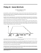
FXAlg #14: Grand Plate Decay Time The reverberation decay time (mid-band ÒRT60Ó), the time required before the reverberation has died away to 60dB below its ÒrunningÓ level. Adjust decay time according to the tempo and articulation of the music. To emulate a plate reverb, this control is typically set from 1 to 5 seconds. HF Damping Adjusts lowpass Þlters in the reverberator so that high frequencies die away more quickly than mid and low frequencies.
FXAlg #15: Finite Verb FXAlg #15: Finite Verb ÒEnvelopedÓ reverberation algorithm Allocation Units: 3 In this algorithm, the left and right sources are summed before being fed into a tapped delay line, which directly simulates the impulse response of a reverberator. The taps are placed in sequence from zero delay to a maximum delay value, at quasi-regular spacings.
FXAlg #15: Finite Verb The Rvb Env control selects 27 cases of envelope gains for the taps. Nine cases emulate a normal forward-evolving reverb, but with some special twists. Cases FWD R1xx have a single reverb peak, with a fast attack and slower decay. The sub cases FWD R1Sx vary the sharpness of the envelope, from dullest (S1) to sharpest (S3). The sub cases FWD R2xx have two peaks; that is, the reverb builds, decays, builds again, and decays again. The sub cases FWD R3xx have three peaks.
FXAlg #15: Finite Verb Rvb Env The Rvb Env control selects 27 cases of envelope gains for the taps. Nine cases emulate a normal forward evolving reverb, another nine emulate a reverb building symmetrically to a peak at the mid point, while the last nine cases emulate a reverse-building reverb. For each major shape, there are three variants of one, two, and three repetitions and three variants of envelope sharpness.
FXAlg #130: Complex Echo FXAlg #130: Complex Echo Multitap delay line effect, consisting of 6 independent output taps and 4 independent feedback taps Allocation Units: 1 Complex Echo is an elaborate delay line with three independent output taps per channel, two independent feedback taps per channel, equal-power output tap panning, feedback diffuser, and high frequency damping. Each channel has three output taps which can each be delayed up to 2600ms (2.6 sec) then panned at the output.
FXAlg #130: Complex Echo Parameters: PAGE 1 Wet/Dry 0 to 100%wet Out Gain Off, -79.0 to 24.
FXAlg #130: Complex Echo R Fdbk2 Dly Adjusts the delay length of the right channelÕs feedback tap, fed back to the left channelÕs delay input. L Tapn Dly, R Tapn Dly Adjusts the delay length of the left and right channelÕs three output taps. L Tapn Lvl, L Tapn Lvl Adjusts the listening level of the left and right channelÕs three output taps. L Tapn Pan, L Tapn Pan Adjusts the equal power pan position of the left and right channelÕs three output taps.
FXAlg #131: 4-Tap Delay ¥ FXAlg #132: 4-Tap Delay BPM FXAlg #131: 4-Tap Delay ¥ FXAlg #132: 4-Tap Delay BPM A stereo four-tap delay with feedback Allocation Units: 1 This is a simple stereo 4-tap delay algorithm with delay lengths defined either in milliseconds (ms) (#131), or in tempos and beats (#132). The left and right channels are fully symmetric (all controls affect both channels). The duration of each stereo delay tap (length of the delay) and the signal level from each stereo tap may be set.
FXAlg #131: 4-Tap Delay ¥ FXAlg #132: 4-Tap Delay BPM The delay lengths for 4-Tap Delay are in units of milliseconds (ms). If you want to base delay lengths on tempo, then the 4-Tap Delay BPM algorithm may be more convenient. The feedback (Fdbk Level) controls how long a sound in the delay line takes to die out. At 100% feedback, the sound will be repeated indefinitely. HF Damping selectively removes high-frequency content from the delayed signal and will also cause the sound to eventually disappear.
FXAlg #131: 4-Tap Delay ¥ FXAlg #132: 4-Tap Delay BPM Dry Bal The left-right balance of the dry signal. A setting of -100% allows only the left dry signal to pass to the left output, while a setting of 100% lets only the right dry signal pass to the right output. At 0%, equal amounts of the left and right dry signals pass to their respective outputs. Hold A switch which when turned on, locks any signal currently in the delay to play until Hold is turned off.
FXAlg #131: 4-Tap Delay ¥ FXAlg #132: 4-Tap Delay BPM Parameters: PAGE 1 Wet/Dry 0 to 100%wet Out Gain Off, -79.0 to 24.
FXAlg #133: 8-Tap Delay ¥ FXAlg #134: 8-Tap Delay BPM FXAlg #133: 8-Tap Delay ¥ FXAlg #134: 8-Tap Delay BPM A stereo eight-tap delay with cross-coupled feedback Allocation Units: 2 This is a simple stereo 8-tap delay algorithm with delay lengths defined in milliseconds (ms) (#133), or in tempos and beats (#134). The left and right channels are fully symmetric (all controls affect both channels).
FXAlg #133: 8-Tap Delay ¥ FXAlg #134: 8-Tap Delay BPM The Hold parameter is a switch which controls signal routing. When turned on, Hold will play whatever signal is in the delay line indefinitely. Hold overrides the feedback parameter and prevents any incoming signal from entering the delay. You may have to practice using the Hold parameter. Each time the sound goes through the delay, it is reduced by the feedback amount.
FXAlg #133: 8-Tap Delay ¥ FXAlg #134: 8-Tap Delay BPM Xcouple 8-Tap Delay is a stereo effect. The cross-coupling control lets you send the feedback from a channel to its own input (0% cross-coupling) or to the other channelÕs input (100% cross-coupling) or somewhere in between. This control has no effect if the Fdbk Level control is set to 0%. HF Damping The -3 dB frequency in Hz of a one-pole lowpass Þlter (-6 dB/octave) placed in front of the delay line.
FXAlg #133: 8-Tap Delay ¥ FXAlg #134: 8-Tap Delay BPM A repetitive loop delay is created by turning up the feedback parameter (Fdbk Level). Only the Loop tap is fed back to the input of the delay, so this is the tap which controls the loop rate. Usually you will want the Loop tap (LoopLength parameter) to be longer than the other tap lengths. To repeat a pattern on a 4/4 measure (4 beats per measure) simply set LoopLength to 4 bts.
FXAlg #135: Spectral 4-Tap ¥ FXAlg #136: Spectral 6-Tap FXAlg #135: Spectral 4-Tap ¥ FXAlg #136: Spectral 6-Tap Tempo based 4- and 6-tap delays with added shapers and resonant comb filters on each tap Allocation Units: 2 for Spectral 4-Tap; 3 for Spectral 6-Tap Spectral 4 Tap and Spectral 6 Tap are respectively 2- and 3-PAU tempo-based multi-tap delay effects. They are similar to simple 4- and 6-tap delays with feedback, but have their feedback and output taps modified with shapers and filters.
FXAlg #135: Spectral 4-Tap ¥ FXAlg #136: Spectral 6-Tap Diffusers add a quality that can be described as ÒsmearingÓ the feedback signal. The more a signal has been regenerated through feedback and consequently fed through the diffuser, the more it is smeared. It requires two parameters, one for the duration a signal is smeared, labeled Diff Delay, and the other for the amount it is smeared, labeled Diff Amt. Positive diffusion settings will add diffusion while maintaining image integrity.
FXAlg #135: Spectral 4-Tap ¥ FXAlg #136: Spectral 6-Tap Each tap also has separate balance and level controls. Since these are tempo based effects, tap delay values and feedback delay (labeled LoopLength on PARAM2) values are set relative to a beat. The beat duration is set be adjusting Tempo in BPM. The tempo can be synced to the system clock by setting Tempo to System.
FXAlg #135: Spectral 4-Tap ¥ FXAlg #136: Spectral 6-Tap PAGE 2 LoopLength On or Off Tap2 Delay 0 to 32 bts Fdbk Image -100 to 100% Tap2 Shapr 0.10 to 6.00 x Tap1 Delay 0 to 32 bts Tap2 Pitch C-1 to C8 Tap1 Shapr 0.10 to 6.00 x Tap2 PtAmt 0 to 100% Tap1 Level 0 to 100% Tap2 Level 0 to 100% Tap1 Bal -100 to 100% Tap2 Bal -100 to 100% Tap3 Delay 0 to 32 bts Tap4 Delay 0 to 32 bts Tap3 Shapr 0.10 to 6.00 x Tap4 Shapr 0.10 to 6.
FXAlg #135: Spectral 4-Tap ¥ FXAlg #136: Spectral 6-Tap Fdbk Image Sets the amount the stereo image is shifted each time it passes through the feedback line. Tap n Delay Adjusts the length of time, in 1/24ths of a beat, each output tap is delayed. Tap n Shapr Adjusts the intensity of the shaper at each output tap. Tap n Pitch Adjusts the frequency in semitones of the comb Þlter at each output tap. Tap n PtAmt Adjusts the intensity of the comb Þlter at each output tap.
FXAlgs #150Ð153: Choruses FXAlgs #150Ð153: Choruses FXAlg #150: Chorus 1 FXAlg #151: Chorus 2 FXAlg #152: Dual Chorus 1 FXAlg #153: Dual Chorus 2 One- and three-tap stereo and dual-mono choruses Allocation Units: 1 for Chorus 1 and Dual Chorus 1; 2 for Chorus 2 and Dual Chorus 2 Chorus is an effect which gives the illusion of multiple voices playing in unison. The effect is achieved by detuning copies of the original signal and summing the detuned copies back with the original.
FXAlgs #150Ð153: Choruses The dual mono choruses are like the stereo choruses but have separate left and right controls. Dual mono choruses also allow you to pan the delay taps between left or right outputs. Dry Feedback Delay L Input High Freq Damping Tap Levels L Output Wet From Right Channel To Right Channel Pan From Right Pans Pan Pan To Right Wet Output Sum Block diagram of left channel of Dual Chorus 2. Right channel is similar. Chorus 1 uses just 1 PAU and has a single delay tap.
FXAlgs #150Ð153: Choruses Dry Feedback Delay L Input High Freq Damping Tap Level From Right Channel To Right Channel L Output Wet Pan From Right Pans To Right Wet Output Sum Block diagram of left channel of Dual Chorus 1. Right channel is similar. The left and right channels pass through their own chorus blocks. There may be cross-coupling between the channels.
FXAlgs #150Ð153: Choruses The settings of the LFO rates and the LFO depths determine how far the LFOs will sweep across their delay lines from the shortest delays to the longest delays (the LFO excursions). The Tap Delays specify the average amount of delay of the LFO-modulated delay linesÑin other words, the timing of the center of the LFO excursion. The center of LFO excursion can not move smoothly, and changing that parameter creates discontinuities in the tapped signal, which is heard as zipper noise.
FXAlgs #150Ð153: Choruses PAGE 2 Tap1 Lvl -100 to 100% Tap1 Dly 4.0 to 1000.0 ms Tap2 Lvl -100 to 100% Tap2 Dly 4.0 to 1000.0 ms Tap3 Lvl -100 to 100% Tap3 Dly 4.0 to 1000.0 ms LFO1 Rate 0.01 to 10.00 Hz LFO1 LRPhs 0.0 to 360.0 deg LFO2 Rate 0.01 to 10.00 Hz LFO2 LRPhs 0.0 to 360.0 deg LFO3 Rate 0.01 to 10.00 Hz LFO3 LRPhs 0.0 to 360.0 deg LFO1 Dpth 0.0 to 50.0 ct LFO2 Dpth 0.0 to 50.0 ct LFO3 Dpth 0.0 to 50.
FXAlgs #150Ð153: Choruses Parameters (Dual Chorus 2): PAGE 1 L Wet/Dry -100 to 100%wet R Wet/Dry -100 to 100%wet L Out Gain Off, -79.0 to 24.0 dB R Out Gain Off, -79.0 to 24.
FXAlgs #150Ð153: Choruses Tap Lvl Levels of the LFO-modulated delay taps. Negative values polarity-invert the signal. Setting any tap level to 0% effectively turns off the delay tap. Since these controls allow the full input level to pass through all the delay taps, a 100% setting on all the summed taps will signiÞcantly boost the wet signal relative to dry. A 50% setting may be more reasonable. Tap Pan The left or right output panning of the delay taps.
FXAlg #154: Flanger 1 ¥ FXAlg #155: Flanger 2 FXAlg #154: Flanger 1 ¥ FXAlg #155: Flanger 2 Multi-tap flangers Allocation Units: 1 for Flanger 1; 2 for Flanger 2 Flanger 1 is a 1-PAU multi-sweep Thru-zero flanger effect with two LFOs per channel. Dry L Input Delay High Freq Damping From Right Channel LFO Tap Levels To Right Channel Static Tap Level L Output Feedback Out Gain Wet Simplified block diagram of the left channel of Flanger 1; the Right channel is similar.
FXAlg #154: Flanger 1 ¥ FXAlg #155: Flanger 2 Flanging was originally created by summing the outputs of two un-locked tape machines while varying their sync by pressing a hand on the outside edge of one reelÑthus the name Òreel-flangingÓ. The key to achieving the flanging effect is the summing of a signal with a time-displaced replica of itself. The result is a series of notches in the frequency spectrum.
FXAlg #154: Flanger 1 ¥ FXAlg #155: Flanger 2 You can set how far each LFO can sweep through the delay line with the excursion controls (Xcurs). The excursion is the maximum distance an LFO will move from the center of its sweep. The total range of an LFO is twice the excursion. You set the delay to the center of LFO excursion with the Dly parameters. The excursion and delay controls both have coarse and fine adjustments.
FXAlg #154: Flanger 1 ¥ FXAlg #155: Flanger 2 sound. It should be obvious that sounds with a richer harmonic structure will be effected in a much more dramatic way than harmonically starved sounds. Having more notches, i.e. a greater Ônotch-densityÕ, should produce an even more intense effect. This increase in notch density may be achieved by having a number of modulating delay lines, all set at the same rate, but different depths. Setting the depths proportionately results in a more pleasing effect.
FXAlg #154: Flanger 1 ¥ FXAlg #155: Flanger 2 PAGE 2 Noise Gain Off, -79.0 to -30.0 dB Noise LP 16 to 25088 Hz StatDlyLvl -100 to 100% L/R Phase 0.0 to 360.0 deg LFO1 Level -100 to 100% LFO1 Phase 0.0 to 360.0 deg LFO2 Level -100 to 100% LFO2 Phase 0.0 to 360.0 deg LFO3 Level -100 to 100% LFO3 Phase 0.0 to 360.0 deg LFO4 Level -100 to 100% LFO4 Phase 0.0 to 360.0 deg PAGE 3 StatDlyCrs 0.0 to 228.0 ms StatDlyFin -127 to 127 samp Xcurs1 Crs 0.0 to 228.0 ms Xcurs3 Crs 0.
FXAlg #154: Flanger 1 ¥ FXAlg #155: Flanger 2 Noise Gain The amount of noise (dB relative to full scale) to add to the input signal. In many ßangers, you can hear the noise ßoor of the signal being ßanged, but in the K2500, if there is no input signal, there is no noise ßoor unless it is explicitly added. [Flanger 2 only] Noise LP The cut-off frequency of a one-pole lowpass Þlter acting on the injected noise. The lowpass removes high frequencies from an otherwise pure white noise signal.
FX Algs #156-160: Phasers FX Algs #156-160: Phasers FXAlg #156: LFO Phaser FXAlg #157: LFO Phaser Twin FXAlg #158: Manual Phaser FXAlg #159: Vibrato Phaser FXAlg #160: SingleLFO Phaser A variety of single notch/bandpass Phasers Allocation Units: 1 (each) A simple phaser is an algorithm which produces a vague swishing or phasey effect.
FX Algs #156-160: Phasers Gain Gain 0 dB 0 dB -20 -20 -40 10 Hz 100 (i) 1000 Freq 10k -40 10 Hz 100 1000 Freq 10k (ii) Response of typical phaser: (i) Wet/Dry = 50% and (ii) Wet/Dry = -50%. Some of the phaser algorithms have feedback. When feedback is used, it can greatly exaggerate the peaks and notches, producing a much more resonant sound. LFO Phaser is a simple phaser algorithm with Wet/Dry and Fdbk Level parameters.
FX Algs #156-160: Phasers Gain 0 dB -20 -40 10 Hz 100 1000 Freq 10k Response of LFO Phaser Twin with Wet/Dry set to 100%. In the Vibrato Phaser algorithm, the bandwidth of the phaser filter can be adjusted exactly like a parametric EQ filter. The In Width controls how the stereo input signal is routed through the effect. At 100% In Width, left input is processed to the left output, and right to right. Lower In Width values narrow the input stereo field until at 0%, the processing is mono.
FX Algs #156-160: Phasers Parameters (SingleLFO Phaser): PAGE 1 Wet/Dry 0 to 100%wet Fdbk Level -100 to 100% Out Gain Off, -79.0 to 24.0 dB PAGE 2 LFO Rate 0.00 to 10.00 Hz N/F Phase CenterFreq 16 to 25088 Hz NotchDepth -79.0 to 6.0 dB FLFO Depth 0 to 5400 ct NLFO Depth 0 to 100% FLFO LRPhs 0.0 to 360.0 deg NLFO LRPhs 0.0 to 360.0 deg Wet/Dry The amount of phaser (wet) signal relative to unaffected (dry) signal as a percent.
FX Algs #156-160: Phasers Parameters (Manual Phaser): PAGE 1 Notch/BP -100 to 100% Out Gain Off, -79.0 to 24.0 dB L Feedback -100 to 100% R Feedback -100 to 100% L Ctr Freq 16 to 25088 Hz R Ctr Freq 16 to 25088 Hz Notch/BP The amount of notch depth or bandpass. At -100% there is a complete notch at the center frequency. At 100% the Þlter response is a peak at the center frequency. 0% is the dry unaffected signal. Out Gain The output gain in decibels (dB) to be applied to the Þnal output.
FX Algs #156-160: Phasers Parameters (Vibrato Phaser): PAGE 1 Wet/Dry -100 to 100%wet Out Gain Off, -79.0 to 24.0 dB CenterFreq 16 to 25088 Hz Bandwidth 0.010 to 5.000 oct LFO Depth 0 to 100% L/R Phase 0.0 to 360.0 deg LFO Rate 0.00 to 10.00 Hz In Width -100 to 100% PAGE 2 Wet/Dry The amount of phaser (wet) signal relative to unaffected (dry) signal as a percent. When set to 50% you get a complete notch. When set to -50%, the response is a bandpass Þlter.
Combination Algorithms [Ò+Ó] Combination Algorithms [Ò+Ó] FXAlg #700 Ñ Chorus+Delay FXAlg #701 Ñ Chorus+4Tap FXAlg #703 Ñ Chor+Dly+Reverb FXAlg #706 Ñ Flange+Delay FXAlg #707 Ñ Flange+4Tap FXAlg #709 Ñ Flan+Dly+Reverb FXAlg #722 Ñ Pitcher+Chor+Dly FXAlg #723 Ñ Pitcher+Flan+Dly A family of combination effect algorithms Allocation Units: 1 or 2 Signal Routing (2 effects) The algorithms listed above with two effects can be arranged in series or parallel.
Combination Algorithms [Ò+Ó] Mix Effect Adjusts the amount of each effect that is mixed together as the algorithm wet signal. Negative values polarity-invert that particular signal. A/Dry->B This parameter controls how much of the A effect is mixed with dry and fed into the B effect. A and B are designated in the algorithm name. This control functions like a wet/dry mix, where 0% is completely dry and 100% is effect A only.
Combination Algorithms [Ò+Ó] Three-Effect Routing: Wet/Dry -100 to 100% Out Gain Off; -79.0 to 24.0 dB L Mix Effect A -100 to 100% R Mix Effect A -100 to 100% L Mix Effect B -100 to 100% R Mix Effect B -100 to 100% L Mix Effect C -100 to 100% R Mix Effect C -100 to 100% A/Dry>B -100 to 100% A/B ->* -100 to 100% */Dry->C -100 to 100% L Mix Effect, R Mix Effect Adjusts the amount of each effect that is mixed together as the algorithm wet signal.
Combination Algorithms [Ò+Ó] Flange: The flangers are basic 1-tap dual flangers. Separate LFO controls are provided for each channel. Slight variations between algorithms exist. Some algorithms offer separate left and right feedback controls, while some offer only one for both channels. Also, cross-coupling and high-frequency damping may be offered in some and not in others. Parameters associated with flange control begin with ÒFlÓ in the parameter name.
Combination Algorithms [Ò+Ó] Dly Time L 0 to 32 bts Dly Time R 0 to 32 bts Dly Fdbk L -100 to 100% Dly Fdbk R -100 to 100% Dly HFDamp 0 to 32 bts Dly Image -100 to 100% Dly Time L, Dly Time R The delay lengths of each channel in beats. The duration of a beat is speciÞed with the Tempo parameter. The delay length in seconds is calculated as beats/tempo * 60 (sec/min). Dly Fdbk L, Dly Fdbk R The amount of the output of the effect that is fed back to the input.
Combination Algorithms [Ò+Ó] Reverb: The reverbs offered in these combination effects is MiniVerb. See FXAlg #1 in this book for information about the parameters. Parameters associated with this reverb begin with ÒRvÓ. Rv Type Hall1 Rv Time 0.5 to 30.0 s; Inf Rv DiffScl 0.00 to 2.00x Rv Density 0.00 to 4.00x Rv SizeScl 0.00 to 4.
Configurable Combination Algorithms [Ò<>Ó] ConÞgurable Combination Algorithms [Ò<>Ó] FXAlg #702 Ñ Chorus<>4Tap FXAlg #704 Ñ Chorus<>Reverb FXAlg #705 Ñ Chorus<>LasrDly FXAlg #708 Ñ Flange<>4Tap FXAlg #710 Ñ Flange<>Reverb FXAlg #711 Ñ Flange<>LasrDly FXAlg #712 Ñ Flange<>Pitcher FXAlg #713 Ñ Flange<>Shaper FXAlg #717 Ñ LasrDly<>Reverb FXAlg #718 Ñ Shaper<>Reverb A family of re-configurable combination effect algorithms Allocation Units: 2 Signal Routing Each of these combination algorithms offer two separ
Configurable Combination Algorithms [Ò<>Ó] A/Dry->B Input 4-Tap Delay Blend 2-Tap Chorus Mix Chorus Mix 4 Tap Wet/Dry Output Blend Out Gain Configured as Ch -> 4T A/Dry->B Input 2-Tap Chorus Blend 4-Tap Delay Mix 4 Tap Mix Chorus Wet/Dry Output Blend Configured as 4T -> Ch Out Gain Algorithm 702, Chor<>4Tap, when A->B cfg is set to (top) ÒCh->4TÓ and (bottom) Ò4T->ChÓ.
Configurable Combination Algorithms [Ò<>Ó] Individual Effect Components Configurable Chorus and Flange: The configurable chorus and flange have 2 moving delay taps per channel. Parameters associated with chorus control begin with ÒChÓ in the parameter name, and those associated with flange begin with ÒFlÓ. General descriptions of chorus and flange functionality can be found in the Chorus (FXAlg #150) or Flange (FXAlg #154) sections of this book.
Configurable Combination Algorithms [Ò<>Ó] Left Left Right Right Control Set 1 Contro l Set 1 LFOR LFO1R Delay Delay Delay Delay LFOL LFO1L Control Set 2 LFO2R Fig. 3 Ñ LFO control in Link1Tap mode LFO2L Fig. 4 Ñ LFO control in Link2Tap mode In addition to the LFO delay taps, the flange offers a static delay tap for creating through-zero flange effects. The maximum delay time for this tap is 230ms and is controlled by the Fl StatDly parameter.
Configurable Combination Algorithms [Ò<>Ó] Flange (PAGE 2): Fl HF Damp 16 to 25088 Hz Fl Xcouple 0 to 100% Fl StatDly 0 to 230 ms Fl StatFB -100 to 100% Fl StatLvl -100 to 100% Fl LFO Lvl -100 to 100% Ch LFO cfg Sets the user interface mode for controlling each of the 4 chorus LFOs. Ch LRPhase Controls the relative phase between left channel LFOs and right channel LFOs.
Configurable Combination Algorithms [Ò<>Ó] inverting the signal. The LsrCntour parameter adds only the Laser Delay portion of the effect, including itÕs own regeneration. For the most intense laser-ness, keep Dly Fdbk at 0% while LsrCntour is enabled. Dly FBImag, Dly Xcouple, Dly HFDamp, and Dly LFDamp are just like those found in other algorithms. Not all Laser Delays in combination algorithms will have all four of these parameters.
Configurable Combination Algorithms [Ò<>Ó] channels through each feedback generation when Dly Fdbk is used. A setting of 0% has no affect. 50% causes equal amounts of signal to be present in both channels causing the image to collapse into a center point source. A setting of 100% causes the left and right channels to swap each regeneration, which is also referred to as Òping-pongingÓ. The regeneration affects of cross-coupling are not heard when LsrCntour is used by itself.
Configurable Combination Algorithms [Ò<>Ó] Reverb: The reverbs offered in these combination effects is MiniVerb. Information about it can be found in the MiniVerb documentation (FXAlg#1 in this book). Parameters associated with this reverb begin with ÒRvÓ. Rv Type Hall1 Rv Time 0.5 to 30.0 s; Inf Rv DiffScl 0.00 to 2.00x Rv Density 0.00 to 4.00x Rv SizeScl 0.00 to 4.
FXAlg #714: Quantize+Flange FXAlg #714: Quantize+Flange Digital quantization followed by flanger. Allocation Units: 1 Digital audio engineers will go to great lengths to remove, or at least hide the effects of digital quantization distortion. In Quantize+Flange we do quite the opposite, making quantization an in-your-face effect. The quantizer will give your sound a dirty, grungy, perhaps industrial sound. As youÕve already gathered from the name, the quantization is followed by a flanger.
FXAlg #714: Quantize+Flange Clearly a one-bit word gives a very crude approximation to the original signal while four bits is beginning to do a good job of reproducing the original decaying sine wave. When a good strong signal is being quantized (its word length is being shortened), quantization usually sounds like additive noise.
FXAlg #714: Quantize+Flange PAGE 2 Fl Tempo System, 1 to 255 BPM Fl Fdbk -100 to 100% Fl Period 0 to 32 bts Fl L Phase 0.0 to 360.0 deg Fl R Phase 0.0 to 360.0 deg Fl StatLvl -100 to 100% Fl LFO Lvl -100 to 100% FlStatDlyC 0.0 to 230.0 ms Fl Xcurs C 0.0 to 230.0 ms FlStatDlyF -127 to 127 samp Fl Xcurs F -127 to 127 samp Fl Delay C 0.0 to 230.
FXAlg #714: Quantize+Flange Fl L/R Phase The phase angles of the left and right LFOs relative to each other and to the system tempo clock, if turned on (see Fl Tempo). In all other respects the right and left channels are symmetric. For example, if one LFO is set to 0° and another is set to 180°, then when one LFO delay tap is at its shortest, the other will be at its longest. If the system tempo clock is on, the LFOs are synchronized to the clock with absolute phase.
FXAlg #715: Dual MovDelay ¥ FXAlg #716: Quad MovDelay FXAlg #715: Dual MovDelay ¥ FXAlg #716: Quad MovDelay Generic dual-mono moving delay lines Allocation Units: Dual MovDelay 1; Quad MovDelay 2 Each of these two algorithms offers generic monaural moving delay lines in a dual mono algorithm. Each separate moving delay can be used as a flanger, chorus, or static delay line selectable by the LFO Mode parameter.
FXAlg #715: Dual MovDelay ¥ FXAlg #716: Quad MovDelay In Quad MovDelay, there are 2 moving delay elements per channel distinguishable by parameters beginning with ÒL1Ó, ÒL2Ó, ÒR1Ó, and ÒR2Ó. The second moving delay on each channel is fed with a mix of the first delays and the input dry signal for that particular channel. These mixes are controlled by L1/Dry->L2 and R1/Dry->R2. Each of the four moving delays have separate Mix and Pan levels. The input dry signal for each channel can also be panned.
FXAlg #715: Dual MovDelay ¥ FXAlg #716: Quad MovDelay PAGE 2 L Delay 0.0 to 1000.0 ms R Delay 0.0 to 1000.0 ms L LFO Mode Flange, ... R LFO Mode Flange, ... L LFO Rate 0.00 to 10.00 Hz R LFO Rate 0.00 to 10.00 Hz L LFO Dpth 0.0 to 200.0% R LFO Dpth 0.0 to 200.0% L Feedback -100 to 100% R Feedback -100 to 100% L HF Damp 16 to 25088 Hz R HF Damp 16 to 25088 Hz Parameters (Quad MovDelay): PAGE 1 L Wet/Dry -100 to 100%wet R Wet/Dry -100 to 100%wet L Out Gain Off; -79.0 to 24.
FXAlg #715: Dual MovDelay ¥ FXAlg #716: Quad MovDelay Ln Mix, Rn Mix Adjusts the mix levels for each moving delay circuit. The resulting sum makes up the wet signal. Negative values polarity-invert the signal. L Pan, R Pan, Ln Pan, Rn Pan The output panning position of each moving delay circuit. 0% is center; Negative values pan left, while positive values pan right. L Dry Pan, R Dry Pan Adjusts the output pan position of the input dry signals. The dry level is controlled with Wet/Dry.
FXAlg #720: MonoPitcher+Chor ¥ FXAlg #721: MonoPitcher+Flan FXAlg #720: MonoPitcher+Chor ¥ FXAlg #721: MonoPitcher+Flan Mono pitcher (filter with harmonically related resonant peaks) algorithm with a chorus or flanger Allocation Units: 2 (each) The mono pitcher algorithm applies a filter which has a series of peaks in the frequency response to the input signal. The peaks may be adjusted so that their frequencies are all multiples of a selectable frequency, all the way up to 24 kHz.
FXAlg #720: MonoPitcher+Chor ¥ FXAlg #721: MonoPitcher+Flan Note that a Pt PkSplit of 100% gives only odd multiples of a fundamental that is one octave down from no splitting. The presence of only odd multiples will produce a hollow sort of sound, like a square wave (which also only has odd harmonics). Curiously enough, at a Pt PkSplit of 50% we also get odd multiples of a frequency that is now two octaves below the original Pitch parameter.
FXAlg #720: MonoPitcher+Chor ¥ FXAlg #721: MonoPitcher+Flan Chorus: The chorus used in FXAlg #720 is a basic dual-channel chorus. Refer to Chorus documentation (FXAlgs #150-153) in this book for more information on the effect. Configurable Flange: The flange in FXAlg #721 is a configurable flange. Refer to the section on Flanger (FXAlg #702 and FXAlgs #154155) in this book for details about this effect.
FXAlg #720: MonoPitcher+Chor ¥ FXAlg #721: MonoPitcher+Flan Fl Xcurs 1 0.0 to 230.0 bts Fl Xcurs 2 0.0 to 230.0 bts Fl Delay 1 0.0 to 230.0 ms Fl Delay 2 0.0 to 230.0 ms Fl Phase 1 0.0 to 360.0 deg Fl Phase 2 0.0 to 360.0 deg Fl Fdbk -100 to 100% Fl HF Damp 16 to 25088 Hz Wet/Dry This is a simple mix of the pitched and chorused or ßanged signal relative to the dry input signal. Out Gain The overall gain or amplitude at the output of the effect.