40” & 60” FINISH CUT C60V H40B H60B OWNER’S MANUAL With Assembly Instructions For Models: H40B, H60B & C60V KUNZ ENGINEERING, INC.
SAFETY INTRODUCTION Your safety, and the safety of others, is very important. To help you make informed decisions about safety, we have provided operating procedures and other information on labels and in this manual. This information alerts you to potential hazards that could hurt you or others. You will find important safety information in a variety of forms, including: Safety Labels – on the mower. Safety Messages – preceded by a safety alert symbol words: DANGER, WARNING, or CAUTION.
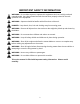
IMPORTANT SAFETY INFORMATION WARNING: Do not allow anyone to operate this equipment who has not fully read and comprehended the safety manual and who has not been properly trained in the safe operation of the equipment. WARNING: Operator should be familiar with all functions of the unit. DANGER: Keep hands, feet, hair and clothing away from moving parts. WARNING: Remove all objects from the work area that might be picked up and thrown by the blades. WARNING: Do not mow when children and others are around.
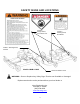
SAFETY SIGNS AND LOCATIONS 275003 – Danger Decal, Cut Hand & Foot 275007 – Warning Decal, Belt Shield 275002 – Warning Decal, General Models H60B & C60V Serial # & Model # Decal WARNING: Clean or Replace Any Safety Signs That Are not Readable or Damaged Replacement decals can be purchased from your local dealer or Kunz Engineering Inc. Mendota, IL 61342 (815) 539-6954 www.kunzeng.
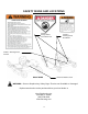
SAFETY SIGNS AND LOCATIONS 275003 – Danger Decal, Cut Hand & Foot 275007 – Warning Decal, Belt Shield 275002 – Warning Decal, General Serial # & Model # Decal Model H40B WARNING: Clean or Replace Any Safety Signs That Are not Readable or Damaged Replacement decals can be purchased from your local dealer or Kunz Engineering Inc. Mendota, IL 61342 (815) 539-6954 www.kunzeng.
ASSEMBLY INSTRUCTIONS READ THE COMPLETE ASSEMBLY INSTRUCTIONS BEFORE STARTING THE ASSEMBLY. You should have: - one mower deck assembly - two caster assemblies - two rear axle assemblies - one tongue assembly (Lawn & Garden Hitching or ATV Tongue) - one tow vehicle hitch assembly (only included on Lawn & Garden Hitching) Optional hitches: - one tongue extension - one rear hitch assembly A. ASSEMBLY OF MOWER WHEELS 1. Set the mower deck assembly on wood blocks so that it is suspended off the ground.
Note: Tighten the four wheel assembly pivot bolts so that the wheel assemblies will not flop down when the deck is raised off the ground. Caster Support Caster Support Stop Tongue Figure 2: Installation of Caster Support Stop B. INSTALLATION OF LAWN & GARDEN HITCHING (refer to the Operation and Adjustment Section for recommended hitching)(if the ATV Tongue was purchased refer to section C. Installation of ATV Tongue) 1.
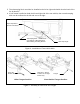
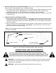
5. The telescoping hitch can either be installed to the left or right and should clear the back of the tire by about 2”. 6. If one mower is pulled on both the left and right side of the tow vehicle, then one telescoping hitch can be mounted to the left and one to the right. Adjust Stop Bolt to Back of Tow Vehicle Telescoping Hitch - Install to Left or to Right or in Both Directions When Pulling Two Wing Mowers.
C. INSTALLATION OF ATV TONGUE ASSEMBLY (if the lawn and garden hitching was purchased refer to Section B. Installation of Lawn & Garden Hitching) 1. The tongue can be installed either on the left or right caster assembly depending on how the wing mower will be towed. See figure 4. Secure the hitch pivot on the chosen caster assembly with the 3/8” x 2-1/2” hex head bolt, lock washer, and nut provided. 2.
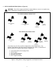
A. HITCH CONFIGURATIONS (Refer to Figure 6) WARNING: Shut off the engine and allow the mower blades to come to a complete stop before adjusting the spreader hitch on the tow vehicle. Tow Vehicle without a Mower Deck 1 & 2 combined or 5 1, 2, & 3 combined or 5 2&4 combined 2&3 combined Tow Vehicle with a Mower Deck 1 & 2 combined or 5 1, 2, & 3 combined 1&2 combined 1, 2, & 3 combined 1&2 combined 2&4 combined Listed above are all of the possible configurations of the wing mowers.
The hitching system is designed so that the wing mower can be pulled directly behind a tow vehicle without a mower deck or as a left or right wing mower when towed behind a tow vehicle with or without a mower deck. If more than one wing mower is towed, they can be pulled in tandem or one on the left and one on the right or a combination of the above conditions until the desired cutting width is obtained. CAUTION: Do not operate two wing mowers in tandem on slopes greater than 25% (1 foot rise, 4 foot run).
C. ADJUSTING CUTTING HEIGHT WARNING: Shut off all engines and allow the mower blades to come to a complete stop on the wing mowers and on the tow vehicle before adjusting the cutting height. The cutting height can be adjusted in a range from 1.0" to 4.0". This is accomplished by adjusting the height adjusting bolts on each of the four corners of the wing mower. See Figure 7. Turn the bolts clockwise to raise the mower cutting height and counter-clockwise to lower the mower cutting height.
4. Adjust the cutting height on the wing mower so that it cuts at the same height as the tow vehicle mower. Adjust each corner of the wing mower so that the distance form the smooth surface to the bottom edge of the deck is equal to the cutting height minus 5/16”. The mower blade cutting edge is 5/16” above the lower edge of the deck. Note: To mow in the lower half of the cutting range, set the front caster axles in the bottom setting and set the anti-scalp wheels in the top hole.
For Model H40B: Set the throttle lever in the choke position to set the choke. (The throttle lever is located on the right side of the engine.) Start engine and move throttle toward slow position to disengage choke. Slow engine speed and engage mower blades clutch handle. (The clutch handle is located at the front of the mower under the engine.) Note: Some belt squealing may occur on engagement. This is normal for a manual clutch engagement design.
F. MOWER OPERATION DANGER: Keep hands, feet, hair and clothing away from moving parts. CAUTION: Clean or replace any safety signs that are not readable or damaged. WARNING: Remove all objects from the work area that might be picked up and thrown by the blades. WARNING: Do not mow when children and others are around. WARNING: Do not fill fuel tank while engine is running or hot. WARNING: Keep all safety shields and deflectors in place during operation.
CAUTION: Do not turn too sharply when the wing mowers are pulled in tandem or pulled behind a zero turn mower. Sharp turns can force the mowers into each other causing damage to the hitches. Listen to the wing mower engines while mowing. The engines should run free and not work too hard. Working the engine too hard will cause overheating and premature failure. Do not allow material to build up on the air inlet to the engine cooling system.
Initial Spring Length 15/16” Running Spring Length 1-1/8” to 1-1/4” Front Engine Figure 8: Belt Pattern and Spring Adjustment (Model H60B) Model C60V: – See Figure 9. Adjust the spring-loaded idler springs to a compressed length of 15/16” initially for a few hours until the belts run in; then adjust the spring to 1-1/8” to 1-1/4” compressed length.
Model H40B – See Figure 10. Take special care to make sure that the belt is placed between the brake stud and the idler pulley. With the clutch engaged, adjust the nuts on the spring-loaded idler adjuster bolt until the length of the spring is approximately 2-3/4”. The running spring length should be maintained between 23/4” and 3-1/4”. For maximum belt life, periodic checks should be done to make sure the spring length has not exceeded the maximum recommended running length.
Note: It is quicker to perform the disengaged spring length and brake stud clearance inspections if done simultaneously. Disengaged Spring Length: This inspection must be performed to make sure that there is proper braking force to prevent the blades from spinning when the clutch is in the disengaged position. With the clutch in the disengaged position measure the spring length. The spring must be between 3-1/4” and 4” to provide the appropriate braking force.
To ease in the blade installation process, use the same block of wood and method used during the removal of the blades. I. LUBRICATION There are up to ten lubrication points on the wing mower -- one spring-loaded idler pivot, two caster wheel pivots, four wheels (on models that apply), and three blade spindles (on models that apply). Lubricate at approximately 10 hr. intervals or more often as required in dusty conditions. Lubricate the blade spindles 2-5 pumps every 50 hours.
WING MOWER SPECIFICATIONS ENGINE: Engine Make Engine Model Cylinders Cycles Crankshaft Engine HP Bore Stroke Displacement Oil Capacity Crankshaft Dia. Key Slot Crankshaft Length Threaded Hole in End of Crankshaft Engine Mounting Bolts Starter Choke MOWER: Fuel Tank Effective Cutting Width Deck Construction Cutting Height Height Adjustment Anti-Scalp Wheels (3" O.D. x 1-1/4" wide) Rear Wheels (Fixed) (2 ply Turf Pnuematic) Front Wheels (Caster) (Semi Pnuematic) Blade Dia.
ACREASE WING MOWER PARTS MODEL C60V Item 1 2 3 4 5 6 7 8 9 10 11 12 13 14 15 16 17 18 19 20 21 21 21 21 21 21 21 22 23 24 25 26 27 28 28 29 30 31 32 Part # 202136 202135 204000 222005 225000 226000 226001 226002 238002 241001 243008 258016 258017 225004 243004 258020 900046 900139 243003 600204 241007 259001 260004 264000 264003 264010 269009 269010 275001 275002 275003 275007 275019 275021 275023 277002 277035 277036 277040 600048 600059 600062 600063 600065 600188 600291 900005 Description Blade Bolt,
Item 33 34 35 36 37 38 39 Part # 900021 900023 900029 900049 900051 900052 900182 24 3000 Description Caster Sup port Contr ol Panel Mower Deck Battery Box Assy. Dep th Gage Tank Support Idler Arm Assy. Bronze Bearing, 1/2"I.D. x 3/4" O.D.
33 11 21 2 8 27 9 35 23 32 2 30 19 20 11 3 6 18 7 39 5 34 28 17 36 1 10 14 13 15 12 22 37 31 16 29 25 24 38 26 4 23 MODEL C60V
ACREASE WING MOWER PARTS MODEL H60B Item 1 2 3 4 5 6 7 8 9 10 11 12 13 14 15 16 17 18 19 20 21 21 21 21 21 21 21 22 23 24 25 26 27 28 28 29 30 31 32 33 Part # 202134 202135 204000 222005 225000 226000 226001 226002 238002 241001 243008 258016 258017 225004 243004 258021 900045 900146 243003 600235 241007 259000 260004 264000 264003 264010 269000 269001 275001 275002 275003 275007 275019 275021 275023 277002 277035 277036 277040 600048 600059 600062 600063 600082 600188 600291 900005 900021 Description B
Item 34 35 36 37 38 39 Part # 900023 900040 24 3000 900042 900049 900051 900052 Description Contr ol Panel Idler Arm Assy. Bronze Bearing, 1/2"I.D. x 3/4" O.D. x 1- 1/2" Long Mower Deck Battery Box Assy.
33 21 26 8 11 2 27 9 19 36 20 32 30 2 3 6 18 11 7 5 17 34 35 1 10 37 28 14 13 15 12 22 38 31 29 4 25 24 39 26 16 23 MODEL H60B
ACREASE WING MOWER PARTS MODEL H40B Item 1 2 3 4 5 6 7 8 9 10 11 12 13 14 15 16 16 16 16 16 16 16 17 18 19 20 21 22 23 24 25 26 27 28 29 30 31 32 Part # 202134 202135 204000 225005 226000 226001 226002 238008 241001 241010 243008 258021 90 0045 90 0146 243003 600235 24 1007 259000 269005 269006 275002 275003 275006 275007 275011 275019 275021 277002 277011 600059 600071 600136 600161 600188 600278 600279 600280 900005 900021 900032 900051 900167 900176 243005 Description Blade Bolt, 3/8"-24NF x 7/8" Hex
28 7 2 11 16 19 8 23 27 3 2 5 22 28 6 11 32 14 9 18 15 31 29 21 4 13 1 24 17 12 25 26 10 20 30 MODEL H40B
LAWN & GARDEN HITCH PARTS 7 6 1 9 8 2 10 5 2 3 4 PARTS LIST Item 1 2 3 4 5 6 7 8 9 10 Part # 202135 216006 600001 600002 900050 600044 600009 600043 900026 900007 Description Hex Head Bolt, 3/8" x 3" Fully Threaded Wire Lock Pin, 3/8" x 2-1/4" Opening Spacer Tongue Pivot Angle Hitch Draw Bar Hitch Adaptor Plate Hitch Stop Angle Hitch Extension Telescope Hitch Short Tongue 29 Quantity 2 2 1 2 1 1 1 1 1 1
ATV TONGUE PARTS 1 3 4 2 PARTS LIST Item 1 2 3 4 Part # 216002 216009 900057 900082 Description Wire Lock Pin .31" X 2.
OPTIONAL EQUIPMENT OPTIONAL FLOATATION KIT This optional floatation kit features an extra front and back tire that can be bolted in the center section of the mower deck. This is a great anti-scalp feature that helps to carry the center section of the mower deck and works well in the following applications: • • • • • Rough, uneven ground where added floatation is needed. Hard to reach areas at the water’s edge around ponds. Extending over a creek banks edge. Steep road banks where added traction is needed.