KR5 UE Relay User Configuration & Monitoring Guide Revision 0.
© Copyright 2020 KUMU NETWORKS INC. ALL RIGHTS RESERVED. Legal Notice This guide contains proprietary data subject to copyright, patent and other security. No whole or portion of this document may be distributed, duplicated or disclosed, without the expressed, earlier, written authorization of Kumu Networks Inc. Use of this guide or the data contained in this for reasons other than those for which it is intended is entirely prohibited. Data provided by Kumu Networks Inc. is accepted to be correct.
Table of Contents Overview......................................................................................................................................... 5 Functionality................................................................................................................................ 5 Features...................................................................................................................................... 7 Interfaces ..............................................
iPerf Utility.................................................................................................................................23 Diagnostic Tools .......................................................................................................................24 Status LED’s .............................................................................................................................26 System Alarms .........................................................................
Overview The document is a User Configuration and Monitoring Guide for the Kumu KR5 UE Relay. The following SKU variants are currently supported: SKU KR5192 KR5181 KR5261 Access LTE Band B2 B3 B7 Backhaul LTE Band Combinations B2 + B12/13/17 B3 + B8/20/28 B7 + B8/20/28 This product is intended for use by a qualified network operator in compliance with local safety regulations and building codes in the country of installation. Product Support: For Technical Support, email techsupport@kumunetworks.
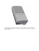
Figure 1 - KR5 Relay The KR5 Relay is designed to be paired with an external eNodeB. The Relay backhauls the eNodeB to another base station over the same access frequencies used by both the eNodeB and the macro network.
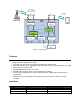
LTE Backhaul Bands 2 + 12/13/17 Bands 3/7 + 8/20/28 Backhaul Antennas BANT1 BANT0 Macro eNB LTE Access Band 2/3/7 Access Antennas Backhaul Duplexer ANT0 KR5 Relay Access Duplexer RX TX ANT1 RX TX UL Canceller Module DL Canceller Module S I M LTE Cat 12 UE ACIN DCIN Relay Application MGT DATA Unduplexer RF0 RF1 Small Cell eNB Figure 2 - System View Features • • • • • • • • • Simultaneous use of same channel for access and backhaul (Full-Duplex) SKU variants for different LTE bands In
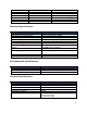
ANT1 RF0 RF1 ETH1 ETH2 ACIN DCIN Nex10 Nex10 Nex10 RJ-45 SFP/RJ-45 Custom Custom Access TX/RX RF I/O TX/RX RF I/O to eNB TX/RX RF I/O to eNB Ethernet I/O to eNB/Config Ethernet I/O to eNB/Config 90V-240VAC power supply -48VDC Electrical Specifications Specification LTE Bandwidths Backhaul Carrier Aggregation eNodeB Tx power eNodeB MIMO UE Tx power UE MIMO Max DL Throughput (PHY) Antenna Isolation (Backhaul - Access) Remote Operations and Maintenance Description 5,10 & 20 MHz 2CC Interband up to 30MHz Up
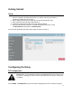
Getting Started Setup 1. Connect a laptop to the KR5 Relay either via a switch or directly to the ETH1 (preferred) or ETH2 port on the relay. 2. Set the laptop ethernet port to DHCP (this is typically already the case) 3. Open a browser and enter http://192.168.100.1 4. Accept the security warning due to the self signed certificate. 5. Enter the administrator username & password.
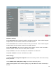
Figure 4 - KUMU Configuration Screen Mandatory Settings Set the DL Earfcn channel number that will be used by the small cell. If the small cell supports multiple bands, enter the channel number for the Band 2 channel. Set the UL Earfcn channel number that will be used by the small cell. If the small cell supports multiple bands, enter the channel number for the Band 2 channel. Setup eNB bandwidth. If the small cell supports multiple bands, enter the value from Band 2. Default is 20MHz.
Set Heartbeat IP to the IP address of the machine to be pinged Set Heartbeat enable as appropriate to enable/disable Finally, select Apply to save the settings. The backhaul connection may be temporarily dropped while the new settings are applied. Site Survey / Setup IMPORTANT: Changing values on this screen will result in the backhaul relaying re-initializing during which the backhaul connection will be lost.
PCI Black List can be also used to Black List specific PCI’s if necessary. In rare cases it may be needed to black list the local small cell to prevent the relay from attempting to attach to it. Network Configuration Select Network -> WAN Setting for network configurations. WAN MTU may need to be configured based on eNodeB preferences. Default value for WAN MTU is 1500.
Device Log The relay supports sending syslog messages to a remote server. Select Management -> Device Log to manage device log location and contents. Default setting is that device does not generate logs. To enable syslog logging: 1. Change Syslog Target to Remote 2. Enter the IP address of the syslog server 3. Set the Severity level as appropriate. It is not recommended to set this any higher than (5) Informational for regular operation.
Select Browse to open a dialog and select a new software installation file (*.ipk). Figure 8 - Software Management Screen This screen also offers the option to backup/restore the relay configuration. To Backup the Configuration: Choose Save to download a backup copy of the relay configuration. Enter a passphrase that will be used to secure the image. To Restore the Configuration: Choose Browse to select a backup file for upload, and then Restore to upload to relay.
About The KR5 Relay About GUI provides useful information about metrics and status of the Relay as shown in Figure 9. Select About from the main menu to check Relay device information including IMEI, Firmware version and LTE Bands supported. Figure 9 - About Screen Performance Status Kumu Cancellation Status Select Kumu -> Basic for basic status information of the Kumu cancellation technology as shown in Figure 10.
changes. During normal operation it will show “in run mode” and 100%. During normal operation both DL State and UL State will show “idle”. At all times the Kumu Configuration will show “Yes”. If any of the above do not go to the intended state within 10 minutes, check the Alarms screen for more information. Heartbeat IP Reachable is user indicate that the configured Heartbeat IP can be contacted and is useful for confirming a valid IP connection.
Figure 12 - LTE Basic Status Screen Select LTE Network -> Status -> Advanced to check LTE TX (PUSCH) and LTE RX (RSRP, SINR) information. Figure 13 - LTE Advanced Status Screen Select LTE Network -> Status -> PDN to check Serving Cell information.
Figure 14 - LTE Serving Cell Screen Network Status Select Network -> Status to check details on LAN and WAN configurations, as shown in Figure 15 Figure 15 - Network Status Screen 18
Select IPv6 -> Status to check IPv6 LAN address configuration. Figure 16 - IPv6 Status Screen Advanced Settings The KR5 Relay GUI allows advanced settings to be configured. These settings should only be changed by qualified operators if required and are not necessary to configure for most normal installations. LTE Settings Band Selection Select LTE Network -> Cell Selection for advanced configurations including to limit bands used for backhaul.
Select LTE Network -> Default PDN for advanced Packet Data Network (PDN) connection parameters. Figure 18 - Default PDN Screen Multiple PDN Select LTE Network -> Multiple PDN if required for multiple Packet Data Network (PDN) connections Figure 19 - Multiple PDN Screen SIM Card PIN (CPIN) Select LTE Network -> PIN to enable PIN code check for SIM card or change the PIN. This is not a common setting as most networks no longer use SIM cards with PIN.
Figure 20 - LAN Settings Screen Select Network -> Port Forwarding to setup port forwarding. These are not necessary for normal operation. Figure 21 - Port Forwarding Screen Select Network -> Port Trigger to setup port triggering. These are not necessary for normal operation Figure 22 - Port Trigger Screen IPv6 Settings Select IPv6 -> Settings to setup Internet connection type and IPv6 LAN address settings.
Figure 23 - IPv6 Settings Screen Firewall Settings Select Firewall -> Basic to enable/disable firewall and basic firewall settings. Figure 24 - Firewall Basic Settings Screen Select Firewall -> Access Restriction to add access restrictions to the Relay.
Figure 25 - Firewall Access Restrictions Screen Monitoring the Relay Status Select Monitoring -> Status for information on CPU Utilization, Memory Utilization, Uplink and Downlink data rates and system information like the last restart reason. Figure 26 - Monitoring Status Screen iPerf Utility Select Monitoring -> iPerf to setup and perform uplink and downlink speed test.
Figure 27 - Iperf Screen Diagnostic Tools Select Monitoring -> Diagnostic Tools to setup diagnostics and observe diagnostic metrics including ping timings and counts or traceout. Ping helps verify if system is connected to the internet or other devices while traceroute can be used to troubleshoot connection routing. Please consult your networking support engineer for use of these tools.
Figure 28 - Ping / Traceroute Screen 25
Status LED’s There are two LEDs on the side of the relay that indicate the state of the relay, as shown in Table 1. Table 1 - LED Status and Recommended Action Red LED Green LED Relay Status Action Flashing Off Booting, not connected Wait 5 – 10 minutes for system to complete boot process.
Figure 29 - Alarms Screen Note: In V33 of the Relay software many alarms will be shown with State=False that have never been activated. These alarms can be ignored.