
Installation Guide
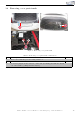


12 Connection CAN High & CAN Low
1
2
2
3
4
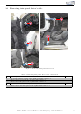
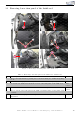
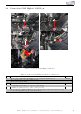
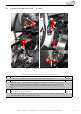
Figure 6: Connection CAN High & CAN Low
Table 4: Connection CAN High & CAN Low - instructions
Nr. Work step Note
1 Remove the air discharge inst all at i on by loos en ing th e marked screw. 1xT20
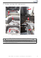
2 Now pull t h e plug out of the CAN gateway.
3 Remove the plug housing.
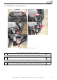
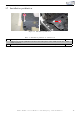
4 Connect CAN High & CAN Low to the plug of the CAN gateway as follows:
- CAN High (black /wh it e ) to pin 16 (orange/b lack)
- CAN Low (black/yellow) to pin 6 (or an ge/br own)
If our cable set consists exclusively of grey wires, please connect the cables according
to the cable inscription at the end of the wires.
Kufatec GmbH & Co. KG - Dahlienstr. 15 - 23795 Bad Segeberg - e-mail: info@kufatec.de 11