
Instruction Manual

8 Assembly Instructions
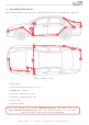
The following illustration shows the cable routing as well as the position of the individual components.
1
2,3
4,5
6
7
1
2
3
4
5
6
7
Figure 3: Vehicle overview
• 1 Front camera
• 2 Ground, steady plus, gateway connection
• 3 FAKRA cable connection
• 4 Side mirror camera driver’s side
• 5 Side mirror camera passenger’s side
• 6 Control unit
• 7 Rear view camera
Please be aware that this overview is only for illustration purposes. Always lay the cable set in the
most convenient and shortest way possible. For a detailed description of the cable routing,
please refer to the relevant sections of the following manual.
Kufatec GmbH & Co. KG - Dahlienstr. 15 - 23795 Bad Segeberg - e-mail: info@kufatec.de 9