
Instruction Manual

8 Assembly Instructions
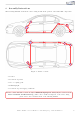
The following illustration shows the cable routing as well as the position of the individual components.
1
2
3,5
4
1
1
2
3,4
3,4
5
Figure 3: Vehicle overview
• 1 Sensor
• 2 Connection ground
• 3 Door coupling point
• 4 Warning light
• 5 Connection power supply / CAN bus
Please be aware that this overview is only for illustration p u rposes. Always lay the cable set in the
most convenient and shortest way possible. For a detailed description of the cable routing,
please refer to the relevant sections of the following manual.
Kufatec GmbH & Co. KG - Dahlienstr. 15 - 23795 Bad Segeberg - e-mail: info@kufatec.de 8