
Instruction Manual


11 Connection cable set
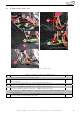
1
2
3
4
4
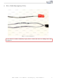
Figure 5: Connection cable set
Table 3: Connection cable set - instructions
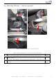
Nr. Work step Note
1 Remove the red and the black marked plug.
2 Connect th e cable for ignition lead (red/white) also to PIN 5 (red/blue cable)
of the red plug.
3 Loosen the grey plug insert out of the black plug and pull it out.
4 Connect CAN High & Low to the grey plu g inser t as foll ows:
Connect CAN High (black/white) also on PIN 3 (yellow/black).
Connect CAN Low (bl ack/yellow) also on PIN 4 (yellow/brown).
If our cable set consists exclusively of grey wires, connect the wires according to the
cable inscription.
4 Connect the control unit as well as the Kufat ec module to the cable set and place
it at the marked position under the carpet.
Kufatec GmbH & Co. KG - Dahlienstr. 15 - 23795 Bad Segeberg - e-mail: info@kufatec.de 10