
Phau Ntawv Qhia


14 Connection cable set
1
2
3
4
5
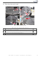
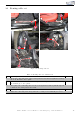
Figure 8: Connection cable set
Table 6: Connection cable set - instructions
Nr. Work step Note
1 Move the marked white plug off from the control unit at the a-pillar of th e passenger’s
side and remove the plug housing.
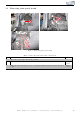
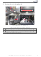
2 Now conn ect CAN High & Low as fol l ows:
- Solder CAN High (black/white) also on PIN 36 (blue/red).
- Solder CAN Low (black/yellow) also on PIN 35 ( re d) .
If our cable set consists exclusively of grey wires, please connect the cables according
to the cable inscription at the end of the wires.
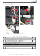
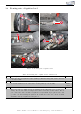
3 Pull the carpet forwar d caref ul l y.
4 Connect the ground cable (brown) also to the marked ground spot under the carpet. 10er
socket
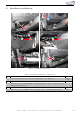
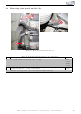
5 Connect the control unit and the module to t he cable set and place them under the
carpet at the marked positions.
Kufatec GmbH & Co. KG - Dahlienstr. 15 - 23795 Bad Segeberg - e-mail: info@kufatec.de 13