
Instruction Manual


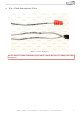


11 Cable connections
1
2
3
4
4
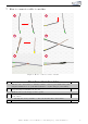
Figure 5: Cable connections
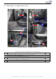
Table 3: Cable connections - instructions
Nr. Work step Note
1 Remove the OBD-Plug by loosening the latch noses and pulling the pl u g out back-
ward s.
2 Connect the cables for CAN High & Low as follows:
CAN High (black/white) to PIN 6 (green)
CAN Low (black/yellow) to PIN 14 (or ange )
3 Connect the ground cable (brown) to the marked ground spot. 1x10er
socket
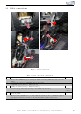
4 Connect the igniti on plus cable (red/white) to t h e marked pink-colored cable down
at the A-pillar.
Measure w i th a multimeter to be sure, that the described cable contains the ignition
plus signal. Otherwise measure to find an alternat i ve ignition plus cable.
Kufatec GmbH & Co. KG - Dahlienstr. 15 - 23795 Bad Segeberg - e-mail: info@kufatec.de 10