
Phau Ntawv Qhia
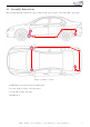


12 Connection CAN-Bus, ignition lead and ground
1
2
3 4
4
5
Figure 5: Connection CAN-Bus, ignition lead and ground
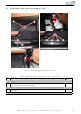
Table 3: Conn ect i on CAN-B us , igni t i on lead and groun d - instr uc ti on s
Nr. Work step Note
1 Move the plug from the airbag control unit off - it is located behind the removed
trim panel - and remove the plug housing.
2 Connect the CAN-Bus wires to the grey plug unit as follows:
- CAN-High (black/white) to the cable of PIN 52 (blue/red)
- CAN-Low (black/yellow) to the cable of PIN 26 (red)
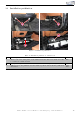
3 The wiring harness, to w hi ch ign i t i on lead is connected, is located in the upper
right field of the passenger ’ s footwell. Connect ignition lead (red/white) to the
green/yellow cable.
4 The marke d ground spot is located in the lower field of the a-pillar, connect the
ground cable (brown) there.
5 Place the module and the control unit behind the carpet of the passenger’s footwell.
Kufatec GmbH & Co. KG - Dahlienstr. 15 - 23795 Bad Segeberg - e-mail: info@kufatec.de 11