
Phau Ntawv Qhia
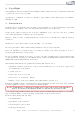


11 Connection Can High & Low / Ground
1
2
3
4
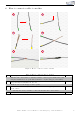
Figure 5: Connection Can High & Low / Ground
Table 3: Instructions for the connection of Can High & Low / Ground
No. Work i ng step Note
1 After you removed the trim panel underneath the dashboard holder, please pull the
cable trench out carefully, which is located in the right footwell behi nd the throttle
pedal.
2 Connect the CAN-wires as follows:
Can high (black/white) to cable color blue-red
Can low (b l ack/yellow) to cable color red
Afterwards please insulate the wires with isolating tape very well.
If our cable set consists exclusively of grey wires, connect the wires according to the
cable inscription at the end of the cables.
3 Please connect the brown cable for ground, as marked. An appropriate ground spot
is situated at the dashboard holder.
1xT20
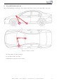
Please connect the cable for ignition plus (red/w hi t e) with a suitable i gni t i on plus
source. Measure with a mult i met e r, on which spot ignition plus is located. A
relevant fuse is in cl u de d in the cable set alr ead y.
4 Connect the control u ni t and the module with the cable set and store both units
underneath the dashboard holder behind the marked OBD-socket. If there is any
hollow space, wh er e the units are arranged, please put some foam material into the
space to avoid clatter.
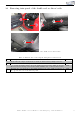
Finally fasten the trim panel of the footwell with the respecti ve screws, which were
removed before.
2xM6
Kufatec GmbH & Co. KG - Dahlienstr. 15 - 23795 Bad Segeberg - e-mail: info@kufatec.de 10