Installation Instructions Complete set Active Sound incl. Soundbooster BMW 1er F-Series v1.1 (12.07.2017) Kufatec GmbH & Co. KG - Dahlienstr. 15 - 23795 Bad Segeberg - e-mail: info@kufatec.
Contents 1 Liability Exclusion 3 2 Copy Right 4 3 General notes 4 4 Safety instructions 5 5 Requirements for the determinable operation 5 6 How to connect a cable to another 6 7 Note Cable Inscription/Color 7 8 Note 7 9 Assembly Instructions 8 10 Removing trim panel of the dashboard on driver’s side 9 11 Connection Can High & Low / Ground 10 12 Cable routing to the sound generator 11 13 Assembly sound generator 12 14 Important Information Sound Booster 13 Kufatec GmbH & Co.
1 Liability Exclusion Dear Customer Our cable sets are developed according to the connection- and circuit diagrams of the corresponding car manufacturer. Before the original production the cable sets will be tested on an original car. Therefore, the integration into the car electronics will be executed according to the instructions of the manufacturer.
2 Copy Right Our installation- and removal instructions, installation plans, software and other documentation with texts or pictures are protected by copy right. A publication or distribution of these documents is only permitted with a written approval of Kufatec GmbH & Co. KG. 3 General notes Regarding the development there has especially been paid attention to your personal safety together with the most possible operating comfort, modern design and actual product technologies.
4 Safety instructions The installation may only be executed by trained qualified personnel. Please execute the installations only in a condition of dead voltage. Here please separate for example the battery from the main power supply and consider the instructions of the car manufacturer. • In order to not endanger your own driving safety please never use security relevant screws, bolts or other fixation pieces at steering, brake system or other components.
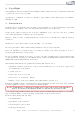
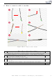
How to connect a cable to another 1 2 3 4 5 6 Figure 1: How to connect a cable to another No. 1 2 3 4 5 6 Table 1: How to connect a cable to another Work step Take the cable of the vehicle, to which you want to connect, (green marked here) and strip the insulation at one point with a suitable tool (cable stripper/cutter knife). Now take the cable of the cable set, which you want to connect, (yellow marked here) and strip the insulation at the end. Twirl the wires of the stripped cable together.
Note Cable Inscription/Color Figure 2: Cable Inscription If our cable set consists exclusively of grey wires, connect the wires according to the cable inscription. 8 Note Make sure that there’s enough space at the described position. If there is no space please cancel the installation and contact our technical support. The use of a sound booster is not permitted without registration in the vehicle papers, in the area of the german StVZO.
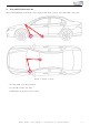
9 Assembly Instructions The following illustration shows the cable routing as well as the position of the individual components. 1,2 3 3 1,2 Figure 3: Vehicle overview • 1 Control unit for sound generation • 2 Sound Booster Pro (module) • 3 External sound generator incl. bracket Kufatec GmbH & Co. KG - Dahlienstr. 15 - 23795 Bad Segeberg - e-mail: info@kufatec.
10 Removing trim panel of the dashboard on driver’s side 2 3 1 3 4 Figure 4: Removing trim panel of the dashboard on driver’s side No. 1 2 3 4 Table 2: Instructions for removing the trim panel on driver’s side Work step Please take the carpet out from the footwell on driver’s side by simple removal. Afterwards remove the trim panel underneath the dashboard holder by ... ... loosening and unscrewing both of the marked screws from the dashboard holder.
11 Connection Can High & Low / Ground 2 1 3 4 Figure 5: Connection Can High & Low / Ground No. 1 2 3 4 Table 3: Instructions for the connection of Can High & Low / Ground Working step After you removed the trim panel underneath the dashboard holder, please pull the cable trench out carefully, which is located in the right footwell behind the throttle pedal.
12 Cable routing to the sound generator 1 2 4 3 4 5 Figure 6: Cable routing to the sound generator No. 1 2 3 4 5 Table 4: Instructions for the cable routing to the sound generator Work step Route the cable set, which was connected with the control unit and the module before, to the marked rubber grommet in the footwell at driver’s side. Aftterwards pull the cable out through the marked rubber grommet into the engine bay at driver’s side, by using a pulling aid.
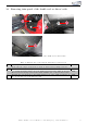
13 Assembly sound generator 2 1 3 3 Figure 7: Assembly sound generator No. 1 2 3 Table 5: Instructions for the assembly of the sound generator Work step Lead the cable through further to the sound generator and fix the sound generator at the rear gear holder by fastening the two screws according to the marking. The heat plate must be adapted to the sound generator with appropriate factory material.
14 Important Information Sound Booster Please use for the fixation of the Sound Booster suitable high tensile screws. In order to avoid losening of the screws by vibration please make the screws safe with appropriate factory material e.g Threadlock. Please additionally check the stability of the Sound Booster regularly and if necessary retighten the screws. In case of no consideration we do not assume liability for possible damages.
List of Figures 1 2 3 4 5 6 7 How to connect a cable to another . . . . . . . . . . . Cable Inscription . . . . . . . . . . . . . . . . . . . . . Vehicle overview . . . . . . . . . . . . . . . . . . . . . Removing trim panel of the dashboard on driver’s side Connection Can High & Low / Ground . . . . . . . . Cable routing to the sound generator . . . . . . . . . . Assembly sound generator . . . . . . . . . . . . . . . . . . . . . . . . . . . . . . . . . . . . . . . . . . . . . . . . . . . . . . . . .