
Datasheet

635
2,5 [0.10]
ø6 H8 [0.24]
ø29
±1
[1.14]
29
±1,5
[1.14]
ø6
H8
[0.24]
4x DIN916 M3 x 4[0.16]
ø10 H8 [0.39]
ø10
H8 [0.39]
9 [0.35]
ø48
±1
[1.89]
46
±2
[1.81]
4x DIN916 M4 x 6[0.24]
ø11 [0.43] H8
(
-
0
0,027
+
)
46
±2
[1.81]
ø48
±1
[1.89]
9
4
JS9
(
-
0
,
0
1
5
0
,
0
1
5
+
)
1
3
,
8
-
0
0
,
1
+
ø12 [0.47] H8
(
-
0
0,027
+
)
4JS9
(
-
0,015
0,015
+
)
1
[0.5]
[0.54]
2
,8
-
0
0
,1
+
ø11 [0.43] H8
(
-
0
0,027
+
)
46
±2
[1.81]
ø48
±1
[1.89]
9
4
JS9
(
-
0
,
0
1
5
0
,
0
1
5
+
)
1
3
,
8
-
0
0
,
1
+
ø12 [0.47] H8
(
-
0
0,027
+
)
4JS9
(
-
0,015
0,015
+
)
1
[0.5]
[0.54]
2
,8
-
0
0
,1
+
ø11 [0.43] H8
(
-
0
0,027
+
)
46
±2
[1.81]
ø48
±1
[1.89]
9
4
JS9
(
-
0
,
0
1
5
0
,
0
1
5
+
)
1
3
,
8
-
0
0
,
1
+
ø12 [0.47] H8
(
-
0
0,027
+
)
4JS9
(
-
0,015
0,015
+
)
1
[0.5]
[0.54]
2
,8
-
0
0
,1
+
Accessories
www.kuebler.com© Fritz Kübler GmbH, subject to errors and changes. 07/2016
Accessories
Connection of motor and encoder Flexible shaft coupling Double loop coupling
The safe, uncomplicated and economical solution, if drive shafts
with angular, radial and/or axial displacement are to be friction-
locked together.
Size 1 Size 2
Max. speed 3000 min
-1
3000 min
-1
Max. torque 0.5 Nm 2.0 Nm
Max. offset of shafts radial ± 2 mm ± 3 mm
axial ± 2 mm ± 4 mm
angular ± 10° ± 12°
Torsion spring stiffness 13 Nm/rad 28 Nm/rad
Radial spring stiffness 13 N/mm 7 N/mm
Moment of inertia 41 gcm² 106 gcm²
Max. clamping torque 100 Ncm 100 Ncm
Weight, approx. 33 g [1.16 oz] 85 g [3.35 oz]
Temperature range -30°C ... + 80°C [-22°F ... +176°F]
Material flange steel galvanized
connecting element Polyurethane
Technical data
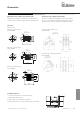
Dimensions
Dimensions in mm
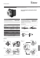
Functional principle
Bore diameter both sides 6 mm [0.24“] 8.0000.1J01.0606 Bore diameter both sides 10 mm [0.39“] 8.0000.1K01.1010
Bore diameter 11 mm [0.43“] and 12 mm [0.47“] 8.0000.1L01.1112
with keyway
Order no. size 1 Order no. size 2
Compensation of a radial misalignment
Compensation of a axial misalignment
Compensation of an angular misalignment
Size 1
6 / 6
[0.24 / 0.24]
Size 2
11 / 12 [0.43 / 0.47]
with keyway
Size 2
10 / 10
[0.39 / 0.39]