
Manual


Page 5 | ENG
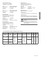
Screw terminals 1 and 2:
Function and max. frequences
(Pulse/Pause 1:1) see Table 2
NPN : active for negative edge
Input resistance: approximately 1 MOhm
Low level: 0…0.7 V DC
High level: 3…30 V DC
PNP : active for positive edge
Input resistance: approximately 100 kOhm
Low level: 0…0.7 V DC
High level: 4…30 V DC
Screw terminal 3:
Reset input, active for negative edge
Contact input / Open Collector NPN
(switching at 0 V DC)
Low level: 0…0.7 V DC
High level: 3…30 V DC
Min. pulse duration: 50 ms
Input resistance: approximately 2.2 MOhm
Screw terminal 4:
Electrical locking of the reset key
Contact input / Open Collector NPN
(switching at 0 V DC)
Low level: 0…0.7 V DC
High level: 3…5 V DC
Input resistance: approximately. 2.2 MOhm
Input not active: Reset key locked
Input in contact
with GND: Reset key unlocked
Screw terminal 5:
Operating mode switch (Mode)
Contact input / Open Collector NPN
(switching at 0 V DC)
Low level: 0…0.7 V DC
High level: 3…5 V DC
Input resistance: approximately 2.2 MOhm
Function: see Table 2
Screw terminal 6:
GND connection common for all inputs
Screw terminal 7:
(–) external power supply for the LCD backlight option
Screw terminal 8:
(+) external power supply for the LCD backlight option
(24 V DC ±20%, 50 mA), Fuse T0.08 A, delayed action
All low voltages, SELV, reinforced/double
insulation.
Signal inputs must be protected with an exter-
nal delayed T0.01 A fuse when the source
does not provide protective impedance (fuse/
current limitation).
english
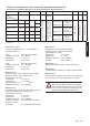
Input specification, pin assignment and adjustable operating modes (DC versions)
A control input (screw terminal 5) allows adjusting the operating mode.
Screw terminal No. 1 No. 2 No. 3 No. 4 No. 5 No. 6 No. 7 No. 8
Designation
Model
INP A INP B Reset Reset
Enable
Control inputs for operating
mode (Mode)
GND
BL
–
BL
+
6.130.012.8x0 07 kHz
NPN 30 Hz NPN
NPN reset input
NPN reset key locking input,
Contact with GND, key free.
not active
=
adding
contact with
GND =
subtracting
GND = 0 V DC
Hintergrundbeleuchtung (–)
Hintergrundbeleuchtung (+)
6.130.012.8x2 12 kHz
PNP NPN
6.131.012.8x0
7 KHz NPN 7 kHz NPN
not active
=
Cnt.Dr Mode
contact with
GND =
Up.Dn Mode
6.131.012.8x1 12 kHz
PNP
12 kHz
PNP
6.133.012.8x0 03 kHz
NPN
3 kHz
NPN
not active
=
Quad Mode
contact with
GND =
Quad2 Mode
6.133.012.8x1 06 kHz
PNP
6 kHz
PNP
Table 2
!
DANGER
Input specification and pin assignment (AC-version)
Screw terminal No. 1 No. 2 No. 3 No. 4 No. 5 No. 6 No. 7 No. 8
Bezeichnung
Typ
INP A
AC/DC
Common
AD/DC
INP B AC/DC Reset Enable
Reset
GND
BL
–
BL
+
6.130.012.8x3 counting
Common connection
for INP A and INP B
reset
NPN reset key locking
input, Contact with
GND. key free.
not
connected
GND = 0 V DC
Backlighting (–)
Backlighting (+)
6.131.012.8x3 subtracting
adding
NPN reset
input
6.132.012.8x3 counting
direction
counting
Table 3