
Manual


Page 4 | ENG
Main technical features:
Display: LCD, 8 decades, height of the figures 8 mm.
Display range:
-9999999…99999999
with leading zeros suppression.
Overflow: In case of a display range overflow, the
counter starts again from 0, but without
removing the leading zeros and activating
all decimal points.
In case of a display range underflow, the
counter starts again from 0 and displays the
minus sign, without removing the leading
zeros and activating all decimal points.
Keys: Electrical locking of the reset key
Housing: Panel mounting, 48 x 24 mm
according to DIN 43 700, RAL 7021
Panel cut-out:
22,2+
0,3 mm
x 45+
0,6 mm
Mounting depth: approximately 48 mm
Weight: approximately 50 g
Protection level: IP65 on the front side
Connection:
Screw terminals, RM 5.00, 8 poles
Rated cross-section: max.: 1 x 1.5 mm
2
2 x 0.75 mm
2
AWG 26-14
EMC: Interference emissions EN 55011 Class B
Interference resistance EN 61000-6-2
Device safety (for the AC models):
Design to: EN 61010 Part 1
Protection Class: Protection Class 2 (front side)
Only the front side is classified as accessible
for the operator.
Application area: Pollution level 2
over-voltage Category II
Insulation:
Front: double insulation,
Rear side: basic insulation, Signal inputs and und sen-
sor power supply: SELV
Power supply:
Non-replaceable lithium battery
(lifetime approximately, 8 years at 20°C)
Working temperature:
–10…+55 °C, relative humidity < 85%,
without condensation
Operating temperature:
–10…+60 °C
Storage temperature:
–20…+70°C
Altitude: to 2000 m
Backlighting:
external electrical source
(24 V DC ±20 %, 50 mA)
SELV, CLASS II (Limited Power Source)
ext. fuse protection T0.08 A
!
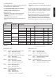
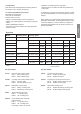
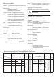
Input specification, pin assignment and adjustable operating modes (DC versions)
A control input (screw terminal 5) allows adjusting the operating mode.
Screw terminal No. 1 No. 2 No. 3 No. 4 No. 5 No. 6 No. 7 No. 8
Designation
Model
INP A INP B Reset Reset
Enable
Control inputs for operating
mode (Mode)
GND
BL
–
BL
+
6.130.012.8x0 07 kHz
NPN 30 Hz NPN
NPN reset input
NPN reset key locking input,
Contact with GND, key free.
not active
=
adding
contact with
GND =
subtracting
GND = 0 V DC
Hintergrundbeleuchtung (–)
Hintergrundbeleuchtung (+)
6.130.012.8x2 12 kHz
PNP NPN
6.131.012.8x0
7 KHz NPN 7 kHz NPN
not active
=
Cnt.Dr Mode
contact with
GND =
Up.Dn Mode
6.131.012.8x1 12 kHz
PNP
12 kHz
PNP
6.133.012.8x0 03 kHz
NPN
3 kHz
NPN
not active
=
Quad Mode
contact with
GND =
Quad2 Mode
6.133.012.8x1 06 kHz
PNP
6 kHz
PNP
Table 2