
Datasheet


92 www.kuebler.com
26.9
[1.059]
34.6 [1.362] 1.65
[0.065]
6.1
[0.24]
5.9
[0.232]
10.16
[0.4]
13.97
[0.55]
13.85
[0.545]
34.6 [1.362]
5
213
[0.197]
0.5 [0.02]
11.65 [0.459]
2.83
[0.6]
Ø
1.6
[0.063]
15.24
[0.111]
26.9 [1.059]
[1.134]
[1.134]
[0.185]
[0.043]
[0.6]
[0.149]
[0.543]
[0.205]
[0.543]
28.8
28.8
4.7
1.1
Ø
1.6 [0.063]
15.24
3.78
1
2
34.7 [1.366]
13.8
5.2
13.8
© Fritz Kübler GmbH, subject to errors and changes. 10/2016
1) Stock types.
1
Mounting pin without el. function 0.4 x 1.2 [0.016 x 0.047]
2
Coil connections 0.4 x 1.2 [0.016 x 0.047]
3
PCB
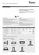
Pulse counters, electromechanical
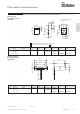
PCB mount, hanging
7-digit display front side
Type K 07.50
Color of housing blue (zinc-plated)
Art. no.
Type Voltage Display 3 V 4.5 V 12 V 24 V
K 07.50 DC (10 Hz) / 0 7 digits 1.130.501.006 1.130.501.008 on request on request
DC (25 Hz) / 1 1.130.501.032 1.130.501.033
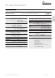
Punching diagram for PCB
(component side)
1
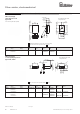
Coil connections 0.4 x 1.2 [0.016 x 0.047]
2
PCB
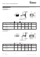
PCB mount, upright
6- and 7-digit display front side
Type K 06.80 / K 07.80
Art. no.
Type Voltage Display 3 V 4.5 V 12 V 24 V 115 V 230 V
K 06.80 DC (10 Hz) / 0 6 digits 1.120.800.006 1.120.800.008 on request on request
DC (25 Hz) / 1 1.120.800.032 1.120.800.033
AC (10 Hz) / a0 1.120.800.051 1.120.800.054 1.120.800.056
K 07.80 DC (10 Hz) / 0 7 digits 1.130.800.006 1.130.800.008 on request on request
DC (25 Hz) / 1 1.130.800.032
1)
1.130.800.033
AC (10 Hz) / a0 1.130.800.051 1.130.800.054 1.130.800.056
Punching diagram for PCB
(component side)
Micro counters K 04 ... K 07 / AK 07High shock resistance (AC+DC)
Dimensions in mm [inch]