
Daim Ntawv Qhia Tus Neeg Siv
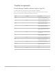
Table Of Contents
- Contents
- Control surfaces
- Mackie Control
- Mackie Control overview
- Mackie Control displays
- Mackie Control channel strips
- Mackie Control assignment buttons
- Mackie Control fader bank buttons
- Function keys
- Modifier buttons
- Automation buttons
- Group button
- Utilities buttons
- Mackie Control transport buttons
- Cursor and zoom keys
- Jog/Scrub wheel
- Programmable user modes
- Foot switches
- Mackie Control assignments
- Assignments overview
- Display buttons table
- Channel strips assignments table
- Assignment buttons table
- Assign Function keys table
- Global View buttons table
- Modifier buttons table
- Automation buttons table
- Utilities buttons table
- Transport buttons table
- Cursor keys table
- Jog/Scrub wheel assignments table
- External inputs table
- M-Audio iControl
- Euphonix devices
- CM Labs Motormix
- Frontier Design TranzPort
- JLCooper CS-32 MiniDesk
- JLCooper FaderMaster 4/100
- JLCooper MCS3
- Korg microKONTROL and KONTROL49
- Mackie Baby HUI
- Mackie HUI
- HUI setup
- HUI assignments
- HUI assignments overview
- HUI assign controls
- HUI fader bank buttons
- HUI window controls
- HUI keyboard shortcuts
- HUI channel strips
- HUI DSP controls
- HUI function keys
- HUI global controls
- HUI automation controls
- HUI status/group controls
- HUI editing controls
- HUI time display
- HUI numeric keypad controls
- HUI transport controls
- HUI cursor buttons
- HUI jog wheel
- HUI foot switches
- Mackie C4
- Novation Launchpad
- Radikal Technologies SAC-2K
- Recording Light
- Roland SI-24
- Tascam US-2400
- Yamaha 01V96
- Yamaha 02R96
- Yamaha DM1000
- Yamaha DM2000
- DM2000 Setup
- DM2000 assignments
- DM2000 Assignments overview
- DM2000 Matrix Select controls
- DM2000 Aux Select controls
- DM2000 Encoder and Fader Mode controls
- DM2000 Display Access controls
- DM2000 Effect/Plug-in controls
- DM2000 LCD display
- DM2000 Track Arming controls
- DM2000 Automix controls
- DM2000 Locator controls
- DM2000 Transport and cursor controls
- DM2000 Channel strips
- DM2000 Assignable keys
- Copyright

82Control Surfaces Support Guide for Logic Pro
CM Labs Motormix faders and pots in Logic Pro
The faders normally control volume. When in Flip mode, however, they duplicate the rotary
encoder assignments.
The table outlines the rotary pot controls and their assignments.
Note:If a modifier button, such as SHIFT, is shown below a button description, it indicates
that the control has an alternate use while the modifier is held down.
Control Modifier Assignment
Rotary pots 1 to 8 Control parameter chosen with the
Rotary Selector, as displayed in the
7 segment display (see below)
7 segment display Shows the current selection for
rotary pots:
Send/EQ editing (S-MUTE or PRE/
PST LED is on):
• S1 to S8 = Send 1 to 8 level
• F1 to F8 = EQ band 1 to 8
frequency
• G1 to G8 = EQ band 1 to 8 gain
• q1 to q8 = EQ band 1 to 8 Q factor
Pan/Surround editing (select LED
is on):
• Pn = Pan
• An = Surround Angle
• dv = Surround Diversity
• FE = Surround LFO
• Sp = Surround Spread
• X = Surround X
• Y = Surround Y
Channel parameter editing (eff-4
LED is on):
• VL = Volume
• Pn or An = Pan/Surround Angle
• FM = Channel input format
• In = Channel input assignment
• Ou = Channel output assignment
• Au = Automation mode
• Gr = Group membership
Assignment:
• d1 to d8 = Assign Send 1 to 8
destination.
Effect editing (DSP/compare LED
is on):
• P1 to 15 = Assign Insert slot 1 to
15 to effect.
• P1. to 15. = Effect parameter
editing
Instrument editing (DSP/compare
LED is on):
• IA = Assign instrument to
Instrument slot.
• IE. = Instrument parameter editing
Group property editing (group LED
is on):
• G1 to 32 = group number