
Daim Ntawv Qhia Tus Neeg Siv
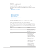

Table Of Contents
- Contents
- Control surfaces
- Mackie Control
- Mackie Control overview
- Mackie Control displays
- Mackie Control channel strips
- Mackie Control assignment buttons
- Mackie Control fader bank buttons
- Function keys
- Modifier buttons
- Automation buttons
- Group button
- Utilities buttons
- Mackie Control transport buttons
- Cursor and zoom keys
- Jog/Scrub wheel
- Programmable user modes
- Foot switches
- Mackie Control assignments
- Assignments overview
- Display buttons table
- Channel strips assignments table
- Assignment buttons table
- Assign Function keys table
- Global View buttons table
- Modifier buttons table
- Automation buttons table
- Utilities buttons table
- Transport buttons table
- Cursor keys table
- Jog/Scrub wheel assignments table
- External inputs table
- M-Audio iControl
- Euphonix devices
- CM Labs Motormix
- Frontier Design TranzPort
- JLCooper CS-32 MiniDesk
- JLCooper FaderMaster 4/100
- JLCooper MCS3
- Korg microKONTROL and KONTROL49
- Mackie Baby HUI
- Mackie HUI
- HUI setup
- HUI assignments
- HUI assignments overview
- HUI assign controls
- HUI fader bank buttons
- HUI window controls
- HUI keyboard shortcuts
- HUI channel strips
- HUI DSP controls
- HUI function keys
- HUI global controls
- HUI automation controls
- HUI status/group controls
- HUI editing controls
- HUI time display
- HUI numeric keypad controls
- HUI transport controls
- HUI cursor buttons
- HUI jog wheel
- HUI foot switches
- Mackie C4
- Novation Launchpad
- Radikal Technologies SAC-2K
- Recording Light
- Roland SI-24
- Tascam US-2400
- Yamaha 01V96
- Yamaha 02R96
- Yamaha DM1000
- Yamaha DM2000
- DM2000 Setup
- DM2000 assignments
- DM2000 Assignments overview
- DM2000 Matrix Select controls
- DM2000 Aux Select controls
- DM2000 Encoder and Fader Mode controls
- DM2000 Display Access controls
- DM2000 Effect/Plug-in controls
- DM2000 LCD display
- DM2000 Track Arming controls
- DM2000 Automix controls
- DM2000 Locator controls
- DM2000 Transport and cursor controls
- DM2000 Channel strips
- DM2000 Assignable keys
- Copyright

198Control Surfaces Support Guide for Logic Pro
DM1000 assignments
Yamaha DM1000 assignments overview in Logic Pro
These sections outline the assignment of YamahaDM1000 interface elements to Logic Pro
functions.
• DM1000 Display Access controls
• DM1000 Aux Select controls
• DM1000 Encoder and Fader Mode controls
• DM1000 LCD controls
• DM1000 LCD display modes
• DM1000 Data entry controls
• DM1000 Channel strips
• DM1000 Stereo channel strip control
• DM1000 Assignable keys
Yamaha DM1000 Display Access controls in Logic Pro
The table outlines the DISPLAY ACCESS controls and their assignments.
Note:A modifier button, such as SHIFT/ADD, shown below a control description indicates
that the control has an alternate use while the modifier is held down. Modifier buttons that
need to be assigned manually by the user are shown with an asterisk (*) that precedes the
button name.
Control Modifier Assignment
AUTOMIX When AUTOMIX is held down in
Channel Display mode, the display
shows the automation mode of the
16 channel strips in the current
bank selection.
PAIR/GROUP Enters Group Edit mode:
• When a channel strip group
is selected, channel strip
membership is indicated by a lit
SEL button. Use this button to
enable/disable the channel strip’s
group membership.
• Virtual encoders 1 to 4 display
properties of the currently
selected group.
• Virtual encoder buttons 1 to 4
enable/disable properties of the
currently selected group.
• When INSERT/PARAM is set to
PARAM, the left and right Tab
Scroll buttons scroll through
the group properties. When set
to INSERT, the buttons scroll
through the groups for editing.