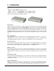
KGS-612F Web Smart 6-Port Gigabit Ethernet Switch with Fiber Connectivity , User s Manual DOC.
(C) 2007 KTI Networks Inc. All rights reserved. No part of this documentation may be reproduced in any form or by any means or used to make any directive work (such as translation or transformation) without permission from KTI Networks Inc. KTI Networks Inc. reserves the right to revise this documentation and to make changes in content from time to time without obligation on the part of KTI Networks Inc. to provide notification of such revision or change.
The information contained in this document is subject to change without prior notice. Copyright (C). All Rights Reserved. TRADEMARKS Ethernet is a registered trademark of Xerox Corp. WARNING: This equipment has been tested and found to comply with the limits for a Class A digital device, pursuant to Part 15 of the FCC Rules. These limits are designed to provide reasonable protection against harmful interference when the equipment is operated in a commercial environment.
Table of Contents 1. Introduction .................................................................................................. 6 1.1 1.2 1.3 1.4 Features ................................................................................................................... 7 Product Panels ......................................................................................................... 7 LED Indicators ...............................................................................................
4. Web Management ....................................................................................... 24 4.1 Start Browser Software and Making Connection ..................................................... 24 4.2 Login to the Switch Unit ........................................................................................... 24 4.3 Main Management Menu .......................................................................................... 25 4.4 System ...........................................
1. Introduction The KGS-612F is a managed Gigabit Ethernet switch which is featured with the following switched ports: Three 10/100/1000Mbps Gigabit copper ports Two combo ports - 10/100/1000Mbps copper & 100Base-FX SFP One combo port - 10/100/1000Mbps copper & 1000Base-X SFP and the following advantages in a small footprint box: Plug and Play The switch is shipped with factory default configuration which behaves like an unmanaged Gigabit switch for workgroup.
1.1 Features Provides 6 10/100/1000Mbps RJ-45, one 1000M SFP and two 100M SFPs Provides in-band web-based management interface All copper ports support auto-negotiation and auto-MDI/MDI-X detection Provides full wire speed forwarding Supports 802.3x flow control for full-duplex and backpressure for half-duplex Provides port status, statistic monitoring and control function Supports port-based and 802.
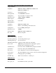
1.3 LED Indicators LED Function POWER Power status LNK/1000M/ACT Network port 1000M link status (Port 1 - Port 6) LNK/100M/ACT Network port 100M link status (Port 1 - Port 6) LNK/10M/ACT Network port 10M link status (Port 1 - Port 6) 1.4 Specifications 10/100/1000 Copper Ports Compliance IEEE 802.3 10Base-T, IEEE 802.3u 100Base-TX, IEEE 802.
Combo Ports with 10/100/1000 RJ-45 and 100Mbps SFP Copper interface Compliance IEEE 802.3 10Base-T, IEEE 802.3u 100Base-TX, IEEE 802.3u 1000Base-T Connectors Shielded RJ-45 jacks Pin assignments Auto MDI/MDI-X detection Configuration Auto-negotiation or software control Transmission rate 10Mbps, 100Mbps, 1000Mbps Duplex support Full/Half duplex Network cable Cat.5 UTP Fiber interface Compliance IEEE 802.
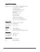
Software Management Functions Interfaces Web browser Management objects System configuration - IP settings, Name, Password Port configuration control and status VLAN function settings Port Link Aggregation function settings Link Aggregation LACP settings RSTP settings 802.1X port access control Port mirroring settings QoS function settings Storm protection control settings Port statistic, LACP status, RSTP status Reboot, restore factory default, update firmware DC Power Input Interfaces DC Jack ( -D 6.
2. Installation 2.1 Unpacking The product package contains: • The switch unit • One power adapter • One product CD-ROM 2.2 Safety Cautions To reduce the risk of bodily injury, electrical shock, fire, and damage to the product, observe the following precautions. • Do not service any product except as explained in your system documentation. • Opening or removing covers may expose you to electrical shock. • Only a trained service technician should service components inside these compartments.
2.4 Mounting the Switch on a Din-rail Chassis The switch also can be mounted on a din-rail chassis. The steps are: 1. Screw the din-rail mounting bracket on the bottom of the switch. 2. Mount the units on a din-rail chassis The din-rail mounting bracket is optional. Consult the place where you purchased the product. 2.5 Applying Power Before you begin the installation, check the AC voltage of your area.
2.6 Reset Button The reset button is used to perform a reset to the switch. It is not used in normal cases and can be used for diagnostic purpose. If any network hanging problem is suspected, it is useful to push the button to reset the switch without turning off the power. Check whether the network is recovered. The button can also be used to restore the software configuration settings to factory default values.
2.8 Making Fiber Connection The SFP slot must be installed with an SFP fiber transceiver for making fiber connection. Your switch may come with some SFP transceivers pre-installed when it is shipped. Installing SFP Fiber Transceiver To install an SFP fiber transceiver into SFP slot, the steps are: 1. Turn off the power to the switch. 2. Insert the SFP fiber transceiver into the SFP slot. Normally, a bail is provided for every SFP transceiver. Hold the bail and make insertion. 3.
2.9 LED Indication LED Function State Interpretation POWER Power status ON OFF The power is supplied to the switch. The power is not supplied to the switch. LNK/1000M/ACT Port link status ON A 1000M link is established. (No traffic) BLINK Port link is up and there is traffic. OFF Port link is down. LNK/100M/ACT Port link status ON A 100M link is established. (No traffic) BLINK Port link is up and there is traffic. OFF Port link is down.
3. Advanced Functions To help a better understanding about the software management interfaces, this chapter describes some advanced functions provided by the switch. 3.1 Abbreviation Ingress Port : Ingress port is the input port on which a packet is received. Egress Port : Egress port is the output port from which a packet is sent out. IEEE 802.1Q Packets : A packet which is embedded with a VLAN Tag field VLAN Tag : In IEEE 802.
3.2 QoS Function The switch provides a powerful Quality of Service (QoS) function to guide the packet forwarding in four priority classes. The versatile classification methods can meet most of the application needs.
3.2.1 Packet Priority Classification Each received packet is examined and classified into one of four priority classes, Class 3, Class 2, Class 1 and Class 0 upon reception. The switch provides the following classification methods: 802.1p classification : use User Priority tag value in the received IEEE 802.1Q packet to map to one priority class DSCP classification : use DSCP value in the received IP packet to map to one priority class Port-based classification : used when 802.
3.3 VLAN Function The switch supports port-based VLAN, 802.1Q Tag VLAN and eight VLAN groups. 3.3.1 VLAN Operation The following figure illustrates the basic VLAN operation flow beginning from a packet received on an ingress port until it is transmitted from an egress port. The following sections describe the VLAN processes and Advanced VLAN mode settings provided by the switch. A global setting means the setting is applied to all ports of the switch.
3.3.2.3 Drop Untag Per Port Setting Enable - All untagged packets and priority-tagged packets are dropped. A priority-tagged packet is treated as an untagged packet in this switch. Only VLAN-tagged packets are admitted. Disable - Disable Untagged packet filtering 3.3.2.4 Drop Tag Per Port Setting Enable - All VLAN-tagged packets are dropped. A priority-tagged packet is treated as an untagged packet in this switch. Only untagged packets are admitted. Disable - Disable VLAN-tagged packet filtering 3.
3.3.5 VLAN Group Table Configuration The switch provides a table of eight VLAN groups to support up to eight VLANs at the same time. Each VLAN group is associated to one unique VLAN. The table is referred for VLAN classification.
3.3.8 Egress Tagging Rules Egress Tagging rules are used to make change to the packet before it is stored into egress queue of an egress port. Three egress settings are provided for each port and are described as follows: 3.3.8.1 Egress Settings Insert Tag (per port setting) Enable Insert the Tag data of the associated Packet Tag information into the packet Disable - No tagging is performed.
An 802.1X authenticator: This is the port on the switch that has services to offer to an end device, provided the device supplies the proper credentials. An 802.1X supplicant: This is the end device; for example, a PC that connects to a switch that is requesting to use the services (port) of the device. The 802.1X supplicant must be able to respond to communicate. An 802.
4. Web Management The switch features an http server which can serve the management requests coming from any web browser software over TCP/IP network. Web Browser Compatible web browser software with JAVA script support Microsoft Internet Explorer 4.0 or later Netscape Communicator 4.x or later Set IP Address for the System Unit Before the switch can be managed from a web browser software, make sure a unique IP address is configured for the switch. 4.
4.3 Main Management Menu Configuration System Switch information, system and IP related settings Ports Port link status, port operation mode configuration VLAN VLAN related configuration Aggregation Port link aggregation (port trunking) related configuration LACP LACP confguration for port link aggregation RSTP RSTP (Rapid spanning tree protocol) related configuration 802.1X 802.
4.
Configuration Description MAC Address The MAC address factory configured for the switch It can not be changed in any cases.
4.4.1 Management VLAN Management VLAN settings allow administrator to access the switch and perform the switch management over a dedicated VLAN. The following rules are applied with the Management VLAN: 1. If the VLAN function is disabled, Management VLAN settings are ignored and no VLAN limitation is applied in accessing the switch web management interface. The switch web (http) server only accepts untagged management packets and replies untagged packets to the management host. 2.
4.
4.5.1 SFP DDM Status DDM (Digital Diagnostic Monitoring) information and status are provided in some SFP transceivers. Part of the information are retrieved and listed as follows: Information Function Port Port number which has SFP slot (Port 4, Port 5, Port 6 come with SFP.
4.6 VLANs VLAN Configuration Description VLAN Disable Select to disable VLAN function All ports are allowed to communicate with each others freely with no VLAN limitation.
4.6.1 Port-based VLAN Mode Configuration Description Group 1, 2 Port-based VLAN group number Member ports Select member ports for the group [Apply] Click to apply the configuration change [Refresh] Click to refresh current configuration [Back] Click to go back to upper menu Operation in this mode: 1. The member ports of two groups are allowed to overlap. 2. The member ports in same group can communicate with other members only. 3. No packet tag is examined. 4.
4.6.
4.6.
4.6.3.
4.6.3.
Note: 1. Priority-tagged packet (VID=0) is treated as untagged packet in the switch. 2. [Tag Aware] setting affects the index used for VLAN classification (VLAN table lookup). The following table lists the index used: Received packet type Untagged Priority-tagged (VID=0) VLAN-tagged (VID>0) Ingress [Tag Aware] setting Tag-ignore Tag-aware PVID PVID PVID PVID PVID Packet tag VID 3. Both [Drop Untag] and [Drop Tag] are set to Disable to admit all packets. 4.6.3.
Configuration Description Port Port number Insert Tag Activate tagging (Insert a tag to the packet) Enable - set to activate tagging Disable - set to disable tagging function Untagging Specific VID No tagging if VID of packet tag information matches [Untagged VID] Enable - set to enable this function Disable - set to disable this function Untagged VID VID for [Untagging Specific VID] setting 1 ~ 4095 - decimal 12-bit VID value [Apply] Click to apply the configuration change [Refresh] Click to ref
4.6.3.4 VLAN Groups Configuration Description Group Group number VID VID of the VLAN to which this group is associated 1 ~ 4095 - decimal 12-bit VID value Member Ports Select the admitted egress ports for the packets belong to the VLAN Port 1 ~ 6 - click to select Source Port Check Check whether the ingress port is the member port of the VLAN Enable - set to enable this check, the packet is dropped if ingress port is not member port of the VLAN.
4.6.4 Important Notes for VLAN Configuration Some considerations should be checked in configuring VLAN settings: 1. Switch VLAN Mode selection It is suggested to evaluate your VLAN application first and plan your VLAN configuration carefully before applying it. Any incorrect setting might cause network problem. 2. Aggregation/Trunking configuration Make sure the members of a link aggregation (trunk) group are configured with same VLAN configuration and are in same VLAN group. 3.
4.7 Aggregation Configuration Description Group Trunk group number Port # Click to select the port as member port of the trunk group [Apply] Click to apply the configuration change [Refresh] Click to refresh current configuration [Back] Click to go back to upper menu Link aggregation function allows to make connection between two switches using more than one physical links. It can increase the connection bandwidth between two switches.
4.8 LACP Configuration Description Port Port number Protocol Enabled Enable LACP support for the port Key Value An integer value assigned to the port that determines which ports are aggregated into an LACP link aggregate. Set same value to the ports in same LACP link aggregate. Value: 1 ~ 255. Auto - key value is assigned by the system [Apply] Click to apply the configuration change [Refresh] Click to refresh current configuration Notes: 1.
4.9 RSTP Configuration Description System Priority The lower the bridge priority is the higher priority it has. Usually, the bridge with the highest bridge priority is the root. Value: 0 ~ 61440 Hello Time Hello Time is used to determine the periodic time to send normal BPDU from designated ports among bridges. It decides how long a bridge should send this message to other bridge to tell I am alive.
Aggregations Enabled to support port trunking in STP. It means a link aggregate is treated as a physical port in RSTP/STP operation. Port Protocol Enabled Port is enabled to support RSTP/STP. Port Edge An Edge Port is a port connected to a device that knows nothing about STP or RSTP. Usually, the connected device is an end station. Edge Ports will immediately transit to forwarding state and skip the listening and learning state because the edge ports cannot create bridging loops in the network.
Configuration Description Mode Disabled - disable 802.1X function Enabled - enable 802.1X function RADIUS IP IP address of the Radius server RADIUS UDP Port The UDP port for authentication requests to the specified Radius server RADIUS Secret The encryption key for use during authentication sessions with the Radius server. It must match the key used on the Radius server. Port Port number Admin State Port 802.
4.10.1 802.
4.11 Mirroring Configuration Description Mirror Port The port is forwarded all packets received on the mirrored ports Mirror Source Select the ports which will be mirrored all received packets to the mirror port.
4.12 Quality of Service QoS Configuration Description Port Port number 802.1p 802.1p priority classification Enable - set to enable this classification to the port for priority-tagged and VLAN-tagged packets Disable - 802.
4.12.1 802.1p Mapping Configuration Description Port n Port number n tag m 3-bit User priority tag value m ( range : 0 ~ 7 ) Priority class Mapped priority class for tag m on Port n Class 3 ~ Class 0 [Apply] Click to apply the configuration change [Refresh] Click to refresh current configuration [Back] Click to go back to upper menu Every ingress port has its own 802.1p mapping table. The table is referred in 802.1p priority classification for the received packet.
4.12.
4.12.
4.13 Storm Control Configuration Description Broadcast Rate The rate limit of the broadcast packets transmitted on a port. Broadcast Rate The rate limit of the Multicast packets transmitted on a port. Flooded Unicast Rate The rate limit of the flooded unicast packets transmitted on a port. The flooded unicast packets are those unicast packets whose destination address is not learned in the MAC address table.
4.
4.15 Detailed Statistics Button Description [Port #] Click to display the detailed statistics of Port #.
4.16 LACP Status Status Description Port The port number Normal Display the ports not LACP enabled.
Status Description Port The port number Protocol Active yes - the port is link up and in LACP operation no - the port is link down or not in LACP operation Partner Port Number The port number of the remote link partner Operation Port Key The operation key generated by the system -56-
4.
4.18 Reboot System This menu is used to reboot the switch unit remotely with current configuration. Starting this menu will make your current http connection lost. You must rebuild the connection to perform any management operation to the unit. 4.19 Restore Default This menu is used to restore all settings of the switch unit with factory default values. Note that this menu might change the current IP address of the switch and make your current http connection lost. 4.
5.
Appendix. Factory Default Settings System Configuration DHCP Enabled Not select (disabled) Fallback IP Address 192.168.0.2 Fallback IP Subnet mask 255.255.255.0 Fallback Gateway IP 192.168.0.1 Management VLAN - VID 0 Management VLAN - CFI 0 Management VLAN - User priority 0 WDT Enable Not select (disabled) Name Null Password 123 SNMP enabled Not select (disabled) SNMP Trap destination 0.0.0.
Ingress Setting - Tag Aware Tag-ignore for all ports Ingress Setting - Keep Tag Enable for all ports Ingress Setting - Drop Untag Disable for all ports Ingress Setting - Drop Tag Disable for all ports Egress Setting - Insert Tag Disable for all ports Egress Setting - Untagging VID Disable for all ports Egress Setting - Untagged VID 1 for all ports VLAN Group 1 - VID 1 VLAN Group 1 - Member Ports Port 1, 2, 3, 4, 5, 6 VLAN Group 1 - Source Port Check Disable VLAN Group 2 - VID 2 VLAN Grou
Protocol Enabled Not select (disabled) for all ports Key Value auto for all ports RSTP System Configuration System Priority 32768 Hello Time 2 Max Age 20 Forward Delay 15 Force Version Normal RSTP Port Configuration Protocol enabled Not select (disabled) for all ports Edge v: Select for all ports Max Age 20 Forward Delay 15 Force Version Normal 802.1X Configuration Mode Disabled RADIUS IP 0.0.0.
Quality of Service Configuration 802.1p Classification Disable for all ports DSCP Classification Disable for all ports Port Priority Class 3 for all ports QoS 802.
DSCP 5 / Priority 0, Class 0 DSCP 6 / Priority 0, Class 0 DSCP 7 / Priority 0, Class 0 All others DSCP Class 0 QoS Service Policy Port 1 Strict priority Port 2 Strict priority Port 3 Strict priority Port 4 Strict priority Port 5 Strict priority Port 6 Strict priority Storm Control Configuration Broadcast Rate No limit Multicast Rate No limit Flooded Unicast Rate No limit -64-