24-Port 10/100Mbps Ethernet Switch User’s Guide
FCC Warning This equipment has been tested and found to comply with the regulations for a Class A digital device, pursuant to Part 15 of the FCC Rules. These limits are designed to provide reasonable protection against harmful interference when the equipment is operated in a commercial environment. This equipment generates, uses, and can radiate radio frequency energy and, if not installed and used in accordance with this user’s guide, may cause harmful interference to radio communications.
UL Warning a) Elevated Operating Ambient Temperature-If installed in a closed or multi-unit rack assembly, the operating ambient temperature of the rack environment may be greater than room ambient. Therefore, consideration should be given to installing the equipment in an environment compatible with the manufacturer's maximum rated ambient temperature (Tmra).
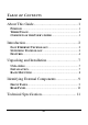
TABLE OF C ONTENTS About This Guide..............................................1 PURPOSE..........................................................................1 TERMS /USAGE .................................................................1 OVERVIEW OF THIS USER’S GUIDE...................................1 Introduction.......................................................2 FAST ETHERNET T ECHNOLOGY .......................................2 SWITCHING TECHNOLOGY........................................
iv
A BOUT T HIS G UIDE Congratulations on your purchase of the 24-port 10/100Mbps Auto-negotiation Fast Ethernet Switch. This device integrates 100Mbps Fast Ethernet and 10Mbps Ethernet network capabilities in a highly flexible package. Purpose This guide discusses how to install your 24-port 10/100Mbps Fast Ethernet Switch.
I NTRODUCTION This chapter describes the features of the Switch and some background information about Ethernet/Fast Ethernet switching technology. Fast Ethernet Technology The growing importance of LANs and the increasing complexity of desktop computing applications are fueling the need for high performance networks. A number of high-speed LAN technologies have been proposed to provide greater bandwidth and improve client/server response times.
packets at the MAC address level of the Ethernet protocol transmitting among connected Ethernet or Fast Ethernet LAN segments. Switching is a cost-effective way of increasing the total network capacity available to users on a local area network. A switch increases capacity and decreases network loading by dividing a local area network into different segments, which don’t compete with each other for network transmission capacity.
Features The Switch were designed for easy installation and high performance in an environment where traffic on the network and the number of user increase continuously. The Switch with its rack size is specifically designed for middle to large workgroups. The Switch provides immediate access to a rapidly growing network through a wide range of user-reliable functions. The Switch is ideal for deployment with multiple high-speed servers for shared bandwidth 10Mbps or 100Mbps workgroups.
ü ü ü ü ü ü ü ü ü ü ü 24-port 10/100BASE Ethernet Switch with RJ-45 connectors Support Auto-negotiation for speed and duplex modes for each port Supports Auto-MDI/MDI-X for each port Wire speed reception and transmission Store -and-Forward switching method Integrated address Look-Up Engine, supports 8K absolute MAC addresses Supports 2.5Mbits RAM for data buffering Front-panel diagnostic LEDs IEEE 802.
U NPACKING AND I NSTALLATION This chapter provides unpacking and setup information for the Switch. Unpacking Open the shipping cartons of the Switch and carefully unpacks its contents.
or in an EIA standard-size equipment rack. For information on rack installation, see the next section, Rack Mounting. When installing the Switch on a level surface, attach the rubber feet to the bottom of each device. The rubber feet cushion the hub and protect the hub case from scratching. Rack Mounting The switch can be mounted in an EIA standard-size, 19-inch rack, which can be placed in a wiring closet with other equipment.
I DENTIFYING E XTERNAL C OMPONENTS This section identifies all the major external components of the switch. Front Panel The figure below shows the front panels of the switch. 24-port 10/100Mbps Fast Ethernet Switch LED Indicator Panel Refer to the next chapter for detailed information about each of the switch’s LED indicators. u Power (PWR) This indicator lights green when the switch is receiving power , otherwise, it is off.
Twisted-Pair Ports These ports supports automatic MDI/MDIX crossover detection function gives true ‘plug and play’ capability without the need of confusing crossover cables or crossover ports. With the Auto-MDI function, you just need to plug-in the network cable to the hub directly and no need to care if the end node is NIC (Network Interface Card) or switches and hubs. Rear Panel AC Power Connector This is a three-pronged connector that supports the power cord.
T ECHNICAL S PECIFICATION General Standards IEEE 802.3 10BASE -T Ethernet IEEE 802.3u 100BASE -TX Fast Ethernet Protocol CSMA/CD Data Transfer Rate Ethernet: 10Mbps (half duplex), 20Mbps (full-duplex) Fast Ethernet: 100Mb ps (half duplex), 200Mbps (full- duplex) Topology Star Network Cables 10BASET: 2 -pair UTP Cat. 3,4,5, EIA/TIA- 568 100-ohm STP 100BASE -TX: 2-pair UTP Cat.