KS-116 16-Port 10/100 Workgroup Switch Installation Guide
We make no warranties with respect to this documentation and disclaim any implied warranties of merchantability, quality, or fitness for any particular purpose. The information in this document is subject to change without notice. We reserve the right to make revisions to this publication without obligation to notify any person or entity of any such changes. Trademarks or brand names mentioned herein are trademarks or registered trademarks of their respective companies.
Installation Guide 16-Port 10/100Mbps Workgroup Switch Sixteen 10/100Mbps RJ45 TX ports /w one MDI uplink port shared with Port 16.
Contents Installation Guide 1. Introduction 1.1 Package Contents 1.2 Installation Procedure 2. Where to Place the Switch 2.1 Placing the Switch onto a Desk or Shelf 2.2 Mounting the Switch onto a Rack 3. Configure The Network Connection 3.1 Connecting Devices to the Switch 3.2 Connecting to Another Ethernet Switch/Hub 3.2.1 MDI to MDX Connect 3.2.2 MDX to MDX Connect 3.3 Application 4. LED Conditions Defined 4.1 LEDs Defined 5. Troubleshooting 5.1 Resolving no Link Conditions 5.
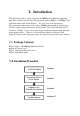
1. Introduction This 16-port Switch is a plug-and-play 10/100Mbps Fast Ethernet switching hub. This switch can auto-sense the operation speed (10Mbps or 100Mbps) and operation mode (full or half duplex). It is very easy to install and use. Every network connection can use up to 200Mbps bandwidth to transfer data because of the switch architecture of the Switch. The total bandwidth of the Switch is 1.6Gbps. Users can use this 16-port Switch to enhance their network performance easily.
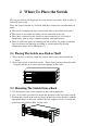
2. Where To Place the Switch This 16-port Switch can be placed on a flat surface (your desk, shelf or table) or mounted onto a rack. Place the 16-port Switch at a location with these connection considerations in mind: l l l l The switch configuration does not break the rules as specified in Section 3. The switch is accessible and cables can be connected easily to it. The cables connected to the switch are away from sources of electrical interference such as radio, computer monitor, and light fixtures.
3. Configure the Network Connection 3.
3.3 Application An Ethernet switch can be used to overcome the hub to hub connectivity limitations as well as improve overall network performance. Switches make intelligent decisions about where to send network traffic based on the destination address of the packet. As a result, the switch can significantly reduce unnecessary traffic. The example below demonstrates the switch ability to segment the network.
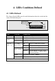
4. LEDs Conditions Defined 4.1 LEDs Defined The 16-port Switch LEDs provide useful information about the switch and the status of all individual ports. Green : Link / Act Yellow : FDX / Col Yellow : 10M / Green : 100M Display Mode 1 2 3 4 5 6 7 8 9 10 11 12 13 14 15 16 Display Mode PUSH Power LED STATUS CONDITION Power ON Switch is receiving power. Display Mode** Green The LED function of Port 1 ~ 16 is "Link / Act".
5. Troubleshooting 5.1 Resolving No Link Conditions The possible causes for a no link LED status are as follow: l l l l The attached device is not powered on The cable may not be the correct type or is faulty The installed building premise cable is faulty The switch port may be faulty Note: Because Port 16 MDI-X port and the MDI port share the same components, if the Port 16 MDI-X port is used, please don't use the MDI port. Or, if the MDI port is used, please don't use the Port 16 MDI-X port. 5.2 Q&A 1.
ü Because the LED of Port 1 ~ 16 can be switched between "Link / Act" or "FDX / Col." functions, please check if the LED display is in the correct display mode. Please refer to Section 4 for LED Display.
A. Product Specifications Access Method Standards Conformance Communication Rate Communication Mode Media Supported Indicator Panel Number of Ports MDI-X/MDI Selection Dimensions Weight Certification Emissions Immunity Power Consumption Input Power Temperature Humidity CSMA/CD, 10 Mbps or 100 Mbps IEEE 802.3 10BASE-T, IEEE 802.
B.
Hub Hub Hub Hub to to to to Server or Workstation Server or Workstation Print Server Print Server 10Mbps 100Mbps 10Mbps 100Mbps Straight-Through, Straight-Through, Straight-Through, Straight-Through, Cat-3,4,5 twisted pair Cat-5 twisted pair Cat-3,4,5 twisted pair Cat-5 twisted pair
C. Compliances EMI Certification FCC Class A Certification (USA) Warning: This equipment generates, uses, and can radiate radio frequency energy and, if not installed and used in accordance with the instruction manual, may cause interference to radio communications.
IEC1000-4-4(1995) 1kV - (power line), 0.5kV - (signal line) This product complies with the requirements of the Low Voltage Directive 73/23/EEC and the EMC Directive 89/336/EEC. Warning! Do not plug a phone jack connector in the RJ-45 port. This may damage this device. D. Warranty We warrant to the original owner that the product delivered in this package will be free from defects in material and workmanship for a period of warranty time from the date of purchase from us or the authorized reseller.