KSD-800M Industrial Managed 8-Port Fast Ethernet Switches with Fiber Connectivity Operation Manual for software v1.082 and later DOC.
(C) 2005 KTI Networks Inc. All rights reserved. No part of this documentation may be reproduced in any form or by any means or used to make any directive work (such as translation or transformation) without permission from KTI Networks Inc. KTI Networks Inc. reserves the right to revise this documentation and to make changes in content from time to time without obligation on the part of KTI Networks Inc. to provide notification of such revision or change.
The information contained in this document is subject to change without prior notice. Copyright (C). All Rights Reserved. TRADEMARKS Ethernet is a registered trademark of Xerox Corp. WARNING: This equipment has been tested and found to comply with the limits for a Class A digital device, pursuant to Part 15 of the FCC Rules. These limits are designed to provide reasonable protection against harmful interference when the equipment is operated in a commercial environment.
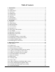
Table of Contents 1. Introduction .................................................................................................. 6 1.1 1.2 1.3 1.4 1.5 1.6 1.7 1.8 Features ................................................................................................................... 7 Product Panels ......................................................................................................... 8 Front Panel ..................................................................................
3.2.4 Packet Forwarding under VLAN ............................................................................ 32 3.2.5 Egress Tagging Rules .......................................................................................... 32 3.2.5.1 Egress Tag Rule (per port setting)..................................................................... 32 3.2.5.2 Null VID Replacement (per port setting) ............................................................. 33 3.2.6 Summary of VLAN Function .................
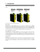
1. Introduction The KSD-800M series are managed 8-port full wire speed Fast Ethernet switches for industrial applications.
Designed for Industrial Applications For industrial environment, the switches are designed with the following enhanced features: High and wide operating temperature Wide operating voltage range for DC power input Power input interface: Screw terminal block and DC jack for adapter Relay output for device power failure alarm DIN rail mounting support for industrial enclosure Panel mounting support for industrial enclosure 1.
1.
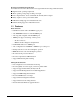
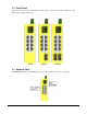
1.3 Front Panel The figure below shows the individual front panel of three model series. The main difference is the number of the equipped fiber ports. 1.4 Network Ports Model 800M provides eight 10/100TX copper ports only. No fiber connectivity is equipped.
Model 800M-1 series provide eight 10/100TX copper ports and one 100FX fiber connector. Port 8 supports dual network cable types. Model 800M-2 series provide eight 10/100TX copper ports and two 100FX fiber connectors. Port 7 and Port 8 support dual network cable types. 1.
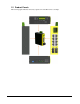
1.6 Top Panel All three model series provide same top panel as figure shown below: The main functions are: DC Power Jack This connector is used when a AC-DC power adapter is used as a power source to the switch.
10/100TX Twisted Pair Ports Compliance IEEE 802.3 10BASE-T, IEEE 802.3u 100BASE-TX Connectors Shielded RJ-45 jacks Pin assignments Auto MDI/MDI-X detection Configuration Auto-negotiation Transmission rate 10Mbps, 100Mbps Duplex support Full/Half duplex Flow control IEEE 802.3x pause frame base for full duplex operation Back pressure for half duplex operation Network cable Cat.5 UTP 100FX Fiber Ports Compliance IEEE 802.
Software Management Functions Interfaces Web, telnet, SNMP MIB-II & private MIB, Traps Management objects Port configuration control and status Username and password settings IP, SNMP related settings VLAN function settings QoS function setting Port Configuration Control Function Configuration P1 ~ P6 Port control function Port TX/RX - enable, disable Port mode - Auto (auto-negotiation), Forced Port speed - 100Mbps, 10Mbps Port duplex - full, half Port Status Port mode, link, speed, duplex VLAN Fu
Redundant Ring Support Configuration Setting for Ring master unit or slave member unit Settings for ring ports and backup port DC Power Input Interfaces Euro type terminal block contacts (DC1 DC2 : 2 sets for power wire cascading) DC Jack ( -D 6.3mm / + D 2.0mm) Operating Input Voltages +7V ~ +30V(+5%) Power consumption Model 800M Model 800M-1 Model 800M-2 4.7W/7.5VDC input, 5.0W/30VDC input 6.0W/7.5VDC input, 6.3W/30VDC input 8.0W/7.5VDC input, 8.
1.8 Model Definitions KSD-800M-xxx Model Ext.
Optical Specifications KSD-800M-xxx Model Ext.FX Connectors -1T FX8 : ST MMF WaveL. TX Power (nm) (dBm) 1310 -19 ~ -14 Rx Sens. (dBm) -31 max. Rx max. (dBm) -14 min. -1C FX8 : SC MMF 1310 -19 ~ -14 -31 max. -14 min. -1C1 FX8 : SC MMF 1310 -20 ~ -14 -31 max. 0 min. -1SA2 FX8 : SC SMF 1310 -15 ~ -8 -31 max. -7 min. -1SL2 FX8 : SC SMF 1310 -15 ~ -8 -30 max. -7 min. -1SL3 FX8 : SC SMF 1310 -15 ~ -8 -34 max. 0 min. -1SL4 FX8 : SC SMF 1310 -5 ~ 0 -35 max. -3 min.
2. Installation 2.1 Unpacking The product package contains: • The switch unit • One DIN-rail mounting kit • One product CD-ROM 2.2 Safety Cautions To reduce the risk of bodily injury, electrical shock, fire, and damage to the equipment, observe the following precautions. • Do not service any product except as explained in your system documentation. • Opening or removing covers may expose you to electrical shock. • Only a trained service technician should service components inside these compartments.
2.3 DIN-Rail Mounting In the product package, a DIN-rail bracket is provided for mounting the switch in a industrial DIN-rail enclosure. The steps to mount the switch onto a DIN rail are: 1. Install the mounting bracket onto the switch unit as shown below: 2. Attach bracket to the lower edge of the DIN rail and push the unit upward a little bit until the bracket can clamp on the upper edge of the DIN rail. 3. Clamp the unit to the DIN rail and make sure it is mounted securely.
2.4 Panel Mounting The switches are provided with an optional panel mounting bracket. The bracket support mounting the switch on a plane surface securely. The mounting steps are: 1. Install the mounting bracket on the switch unit. 2. Screw the bracket on the switch unit.
3. Screw the switch unit on a panel.
2.5 Applying Power The power specifications of the switch are: Operating Voltage Power Consumption +7 ~ +30VDC Max. 8.3W @30VDC The switch provides two types of power interfaces, terminal block and DC power jack for receiving DC power input from external power supply. Using Terminal Blocks Either DC1 interface or DC2 interface can be used to receive DC power from an external power system. Or, DC2 also can be used to deliver the power received on DC1 to next switch in cascading way.
Using DC Power Jack When an external power system is not available, the switch provides a DC jack to receive power from typical AC-DC power adapter alternatively. AC Power Adapters: Optional commercial rated adapters are available for purchasing. Rated AC120V/60Hz DC7.5V 1.5A Rated AC230V/50Hz DC7.5V 1.5A Rated AC100V/50-60Hz DC7.5V 1.5A Rated AC240V/50Hz DC7.5V 1.5A Note: Before you begin the installation, check the AC voltage of your area.
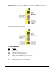
2.7 Reset Button The reset button is used to perform a reset to the switch. It is not used in normal cases and can be used for diagnostic purpose. If any network hanging problem is suspected, it is useful to push the button to reset the switch without turning off the power. Check whether the network is recovered. The button can also be used to restore the software configuration settings to factory default values.
2.9 Making Fiber Connections FX7 port and FX8 port operate on 100Mbps and full duplex. The following figure illustrates a connection example between two fiber ports: Make sure the Rx-to-Tx connection rule is followed on the both ends of the fiber cable. Far End Fault Function The FX ports are facilitated with this function, which conforms to IEEE 802.3u 100BASE-FX specifications.
2.10 LED Indication LED Function State Interpretation PWR Power status ON OFF The power is supplied to the switch. The power is not supplied to the switch. LNK Port link status ON An active link is established on the port. (No traffic) BLINK Port link is up and there is traffic. OFF Port link is down. 100M Port speed status ON OFF FX7 FX7 link status ON FX7 port is link up. BLINK Port link is up and there is traffic. OFF Port link is down. FX8 FX8 link status ON FX8 port is link up.
2.11 Configuring IP Address for the Switch The switch is shipped with the following factory default settings for software management : Default IP address of the switch : 192.168.0.2 / 255.255.255.0 The IP Address is an identification of the switch in a TCP/IP network. Each switch should be designated a new and unique IP address in the network. Refer to Telnet management interface. To change the default IP address Use Telnet IP menu. 2.
3. Advanced Functions To help a better understanding about the software management interfaces, this chapter describes some advanced functions provided by the switch. 3.1 QoS Function The switch provides a powerful Quality of Service (QoS) function to guide the packet forwarding in two priority levels. The versatile classification methods can meet most of the application needs.
3.1.3.1 Port-based Priority Setting (per port setting) As one port is configured to be enabled for port-based priority, all received packets on the port will be classified as high priority. The options are: Enable - All packets received on the port are classified as high priority Disable - Port-based classification is not applied. 3.1.3.2 802.1p Classification (per port setting) For a received 802.
3.1.3.4 IP Network Address Classification User can configured two IP network address settings, IP(A) and IP(B). If a received IP packet’s source address or destination address belongs to the user defined IP network addresses. The packet is classified as high priority. User Defined IP(A) Classification (Global) Enable - Enable IP(A) checking Disable - IP(A) classification is not applied.
3.2 VLAN Function The switch supports port-based VLAN, 802.1Q Tag Aware VLAN and eight VLAN groups. Some VLAN related terminologies are described as follows: VLAN Group VLAN group specifies a VLAN information that can be referred by the switch in performing VLAN mapping and packet forwarding for ingress port and the received packets.
The following sections describe the VLAN processes and related settings provided by the switch. A global setting means the setting is applied to all ports of the switch. A per port setting means each port can be configured for the setting respectively. 3.2.2 Ingress Rules When a packet is received on an ingress port, the ingress rules are applied for packet filtering and mapping a VLAN group. The first rule is : 3.2.2.1 802.1Q Tag Aware VLAN Mode (global setting) Enable - 802.
3.2.3 VLAN Group Mapping The VLAN group mapping is the switch’s decision process to find a right VLAN group for the received packet when it is not filtered by ingress rules. The group mapping depends on the VLAN mode and the packet type. The following table lists the decision rules: VLAN Mode 802.1Q Tag Aware Packet Type Tagged & non-Null 802.1Q Tag Aware 802.
3.2.5.2 Null VID Replacement (per port setting) The null VID of a Null VID packet will be replaced with the associated ingress port’s PVID. This setting still works even Egress Tag rule : [PVID insertion for untagged packets only] is selected. 3.2.6 Summary of VLAN Function Number of VLAN groups : 8 groups at the same time VLAN ID supported : 1 ~ 4095 (12-bit VID) VLAN mode options : 802.
In building a redundant ring network configuration, the backup link must be connected securely and has no risk for failure. The switch provides a user friendly management interface to configure the ring network. It also provides a helpful function to examine the status of all members in a ring. Refer to section 5.4.5 for more information about how to configure a ring network. 3.3.2 Fault Monitoring & Activating Backup Link The master monitors the network continously.
4. Software Management The switch provides the following in-band management interfaces for configuring the switch to meet requirements for different applications: • Telnet over TCP/IP • Http web-based over TCP/IP • SNMP over TCP/IP 4.1 Telnet Management Interface Use Telnet software to perform the management operation. The most convenient solution is using the built-in Telnet function in your Windows PC. Execute Telnet command as follows: >telnet xxx.xxx.xxx.xxx The specified xxx.xxx.xxx.
4.2 IP Menu Select [1] IP Menu to configure IP protocol related settings for the switch. IP Menu: [0] Print this menu [1] Set IP Address [2] View IP status [Q] Back Menu Please Select(0-3).... INET>1 Enter Esc to abort.. Please Input IP Address(xxx.xxx.xxx.xxx):192.168.0.232 replacing net[0] IP address192.168.0.232 with 192.168.0.232 Please Input Subnet Mask(xxx.xxx.xxx.xxx):255.255.255.0 replacing subnet mask[0]255.255.255.0 with 255.255.255.0 Please Input Gateway IP(xxx.xxx.xxx.xxx):192.168.0.
4.3 SNMP Menu This menu is used for configuring SNMP protocol related settings. Snmp Menu: [0] Print this menu [1] View Snmp Setting [2] Set Snmp Name [3] Set Snmp Location [4] Set Snmp Contact [5] Set Snmp Community [6] Set Snmp Trap Manager [7] Set Port Link Trap Function [8] Set Login Failure Trap Function [Q] Back Menu Please Select(0-9)....
4.4 Port Config Select [3] Port Config to configure port configuration.
Speed Control Speed configuration when auto-negotiation is disabled 100M - 100Mbps 10M - 10Mbps Duplex Control Duplex configuration when auto-negotiation is disabled Full - full duplex Half - half duplex Select [2] Port Config to view current port status for all ports as example below: Port Setting Description Ports Select port range to be configured. More than one group can be configured at the same time.
Select [1] VLAN Group Information to view all groups.
VLAN Global Settings Description 802.1Q Tag Aware Mode Enable - Under this mode, the switch will check the content of every received packets. For 802.1Q tagged packets, the tagged VID on the packet is used to look up the VLAN group table and find the group whose VID matches the packet tagged VID. Disable - Under this mode, the switch does not check the contents of the received packets. The default VLAN group indexed by the ingress port is used directly for further VLAN operation.
Select [6] VLAN Per Port Settings to configure VLAN ID for VLAN groups. VLAN Per Port Settings: Port Default Unmatched Egress Null No. Group VID tag rule VID +-----+--------+-----------+---------+---------+ 1 1 Disabled 4 Disabled 2 1 Disabled 4 Disabled 3 1 Disabled 4 Disabled 4 1 Disabled 4 Disabled 5 1 Disabled 4 Disabled 6 1 Disabled 4 Disabled 7 1 Disabled 4 Disabled 8 1 Disabled 4 Disabled +-----+--------+-----------+---------+---------+ Enter Esc to abort..
Null VID The null VID of a Null VID packet will be replaced with the associated ingress port’s PVID. This setting still works even Egress Tag rule : [PVID insertion for untagged packets only] is selected. Enable - Null VID is replaced with Port’s PVID for Null VID packets Disable - Null VID replacement rule is not applied. 4.5.2 Administrator -> QoS Settings Select [4] Administrator -> [2] QoS Settings to configure QoS function related settings for the switch.
listed below, the packet is classified as high priority. EF - <101110>, AF - <001010> <010010> <011010> <100010> and Network Control - <111000> <110000> Disable - Default DSCP classification is not applied. Select [2] QoS Other Settings to configure QoS global settings: QoS Other Settings: [0] Print this menu [1] Show QoS Other Status [2] 802.
Select [2] - [5] to configure other settings as follows: QoS Other Settings Description 802.1p priority tag 802.1p High Priority Tag Threshold Setting for 802.
4.6 Restore Default Values Select [6] Restore Default Values to restore all settings of the switch back to factory default values. Do you want to restore system default settings?(Y/N): Refer to Appendix for factory default values. 4.7 Security Manager Select [7] Security Manager to change user name and password. The user name and password are used for access authentication to the switch in telnet management and web management. Current username: admin Current password: ******** Press ESC to abort ...
4.8 Update Firmware Select [7] Update Firmware to update the firmware of the switch. A new firmware may be released by the factory due to function enhancement. The update method is via TFTP protocol. The steps are: 1. A TFTP server must be available in the network before updating the firmware. 2. Place the new firmware on the TFTP server with filename [image.bin]. 3. Use [7] Update firmware to specify the IP address of the TFTP server and start downloading of the new firmware as follows: Enter Esc to abort.
5. Web Management The switch features an http server which can serve the management requests coming from any web browser software over internet or intranet network. Web Browser Compatible web browser software with JAVA support Microsoft Internet Explorer 4.0 or later Netscape Communicator 4.x or later Set IP Address for the System Unit Before the switch can be managed from a web browser software, make sure a unique IP address is configured for the switch. 5.
The following screen shows welcome screen when a successful login is performed. In addition to the device image, the screen supports the following menus on the right side: 1. Home : home page and device image 2. Port Status : view all switched port status 3.
5.3 Port Status Menu Click >Port Status Menu to display the port status for all switched ports.
5.
IP Address IP Address Setting Description IP Address IP address for the switch Submask Subnet mask of the IP address Gateway IP address of the default gateway SNMP Entries SNMP settings include system settings, community settings and Snmp trap settings as follows: System Settings Description Name Set a system name for the switch Location Set the location where the switch unit is installed Contact Set the contact person for the switch unit -52-
Community Settings Description Community String Community strings which are allowed to access the switch unit via SNMP protocol Access Right The access right assigned to the community string, options are: RO - read only RW - read / write <> Add one new community string specified in String box. Up to 4 community strings are allowed. Remove Remove the specified community string from list.
Trap Manager Settings Description IP Address Specify the IP address of the trap manager to which the switch will send Snmp traps when predefined events occur.
Speed Control Select port speed when auto-negotiation is disabled, options: Null - unchanged 100M - 100Mbps 10M - 10Mbps Duplex Control Select port duplex when auto-negotiation is disabled, options: Null - unchanged Full - full duplex Half - half duplex Apply Button to confirm the settings The current port settings for all ports are also listed below the control dialog window. 5.4.3 VLAN Controls VLAN settings are divided into three categories: 1.
Global Settings Description VLAN VLAN Select Enable VLAN - Enable switch VLAN function Disable VLAN - disable switch VLAN function Ingress Rules 802.1Q tag aware VLAN Enable - Under this mode, the switch will check the content of every received packets. For 802.1Q tagged packets, the tagged VID on the packet is used to look up the VLAN group table and find the group whose VID matches the packet’s tagged VID. Disable - Under this mode, the switch does not check the contents of the received packets.
Group Settings Description Groups Specify the VLAN group for member port configuration Port Specify the port to be added into or deleted from the specified group.
Per Port Settings Per Port Settings Description Port Select port list for configuration. Ingress Rules Default Group Index to the default VLAN group of the selected ports, group 1 ~ 8 Unmatched VID N - unchanged Enable - Drop the tagged packet if the packet VID does not match the ingress port PVID Disable - No Unmatched VID filtering is applied to the port Egress Rules Egress tag rule This tagging rule is used to make change to the packet before it is transmitted out from an egress port.
Tagged packet : the packet tag VID is replaced with ingress port PVID as new tag VID 2 Untagging for all packets Untagged packet : the packet is not modified Tagged packet : the packet tag VID is removed and becomes an untagged packet Null VID packet : depending on next Null VID Replacement setting 3 Ingress PVID insertion for untagged packets only Untagged packet : the packet is inserted with the associated ingress port PVID as tag VID Tagged packet : the packet is not modified 4 No tag insertion and tag r
5.4.4 QoS Controls QoS settings are divided into two categories: 1. Per Port Settings - QoS settings for each port 2. Other Settings - Some global QoS settings QoS Per Port Settings Description Port Select port list for the per port QoS configuration. Port based priority Port based priority classification Enable - All packets received on the port are classified as high priority Disable - Port-based classification is not applied. N - unchanged 802.
QoS Global Settings Description 802.1p high priority threshold 802.1p High Priority Tag Setting for 802.
Specific Mask (A) Enter user defined IP(A) subnet mask for classification. IP(A) address and IP(A) subnet mask specify IP(A) user defined IP network address for IP packet classification. Specific IP & Mask (B) If a received IP packet’s source address or destination address belongs to the user defined IP network addresses. The packet is classified as high priority. Enable - Enable user defined IP(B) network address checking Disable - IP(B) classification is not applied.
5.4.5 Redundant Ring Before configuring, refer to section 3.3 first for the operation of a ring network.
Ring & Port Status Description Ring Status Display the current status in a redundant ring operation STANDBY - the ring is under fault monitoring (on guard) BACKUP - the backup link is activated and ring enters into backup state Port No.
Ring & Port Status Description MAC Address The MAC address of the switch found in a ring Ring Status The ring status of the switch in First Port The specified 1st port of the switch for the ring connection First Port / Port The port number of the specified 1st port First Port / Set The port ring function of the specified 1st port Ring - the port function is a ring port Backup - the port function is a backup port First Port / Link The port link status of the specified 1st port in a ring Up - the
When the standby backup link is activated, the port status display is: [Ring List] can also be used to display the whole ring status upon fault as example illustrated below: The backup link is activated and the ring is using backup link and in backup status now. The fault is caused by the cable connected on Switch 1 Port 7 and Switch 2 Port 7. 5.4.5.
Button Description Apply Button to save the configuration Recover Button to release blocked switches and failed section after network fault repairing Note : it may not recover the whole failed section by just one click especially in the case when multiple faults occur at the same time. Click and use [Ring List] button to display ring status until the recovery is complete.
5.4.7 Security Manager This menu is used to change the user name and password. User name and password are used for access login in telnet and web management interfaces of the switch. Settings Description User Name New user name Assign/Change password New password Reconfirm password Retype the new password 5.4.8 Image Refresh Time The switch image shown in web pages is updated periodically to present the latest status. The default time interval of refreshing the image is 20 seconds.
5.4.9 Update Firmware This menu is used to perform firmware (switch software) upgrade via TFTP protocol. Before doing TFTP operation, one TFTP server must be available in the network to where this switch is connected and the new firmware file image.bin is placed in the server. Settings Description TFTP Server IP Address Specify the IP address of the TFTP server Firmware File Name Specify the file name of the new firmware Apply Button to confirm the settings 5.4.
6. SNMP Management The switch supports SNMP v1 protocol for SNMP management. One device MIB file is provided in the product CD. The MIB file is used for SNMP management software to set or get the management information objects provided in the switch. 6.1 MIB Objects The device private management objects provided by the SNMP agent in the switch are: Objects OID Description Enterprise 867 Manufacturer ID Device 37 Device ID (Snmp agent) Software 867.37.1.1 867.37.1.
Appendix. Factory Default Settings IP Settings IP Address 192.168.0.2 IP Subnet mask 255.255.255.0 Gateway IP 192.168.0.
VLAN group 6 member : P6, VID : 6 VLAN group 7 member : P7, VID : 7 VLAN group 8 member : P8, VID : 8 VLAN group 9 member : P1 - P8, VID : 128 Default VLAN group index 1 (group 1) for Port 1 - Port 8, 9 (group 9) for management port Unmatched VID Disabled for Port 1 - Port 8 Egress tag rule 4 for Port 1 - Port 8 Null VID replacement Disabled for Port 1 - Port 8 QoS Settings Port based priority Disabled for Port 1 - Port 8 802.