KGD-600 Industrial Web Smart 6-Port Gigabit Ethernet Switch with Fiber Connectivity Installation Guide DOC.
(C) 2006 KTI Networks Inc. All rights reserved. No part of this documentation may be reproduced in any form or by any means or used to make any directive work (such as translation or transformation) without permission from KTI Networks Inc. KTI Networks Inc. reserves the right to revise this documentation and to make changes in content from time to time without obligation on the part of KTI Networks Inc. to provide notification of such revision or change.
The information contained in this document is subject to change without prior notice. Copyright (C). All Rights Reserved. TRADEMARKS Ethernet is a registered trademark of Xerox Corp. WARNING: This equipment has been tested and found to comply with the limits for a Class A digital device, pursuant to Part 15 of the FCC Rules. These limits are designed to provide reasonable protection against harmful interference when the equipment is operated in a commercial environment.
Table of Contents 1. Introduction .................................................................................................. 6 1.1 1.2 1.3 1.4 Features ................................................................................................................... 7 Product Panels ......................................................................................................... 8 LED Indicators ...............................................................................................
4. Web Management ....................................................................................... 27 4.1 Start Browser Software and Making Connection ..................................................... 27 4.2 Login to the Switch Unit ........................................................................................... 27 4.3 Main Management Menu .......................................................................................... 28 4.4 System ...........................................
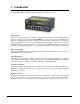
1. Introduction The KGD-600 is a managed 6-port Gigabit Ethernet switch which is featured with five copper ports, one mini-GBIC (SFP) port and the following advantages in a small footprint box: Plug and Play The switch is shipped with factory default configuration which behaves like an unmanaged Gigabit switch for workgroup. It provides five 10/100/1000Mbps copper ports for connections to Ethernet, Fast Ethernet, and Gigabit Ethernet devices.
Industrial Features For industrial environment, the devices are designed with the following enhanced features exceeding that of commercial Ethernet switches: • High and wide operating Temperature • Power input interface: Industrial screw terminal block and DC power jack for external commercial power adapter as option • Screw panel and DIN rail mounting support for industrial enclosure • Industrial-rated Emission and Immunity performance 1.
1.
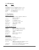
1.3 LED Indicators LED Function POWER Power status LNK/1000M/ACT Network port 1000M link status (Port 1 - Port 5) LNK/100M/ACT Network port 100M link status (Port 1 - Port 5) LNK/10M/ACT Network port 10M link status (Port 1 - Port 5) P6 LNK Port 6 1000M link status P6 OL Port 6 optical link status 1.4 Specifications 10/100/1000 Copper Ports Compliance IEEE 802.3 10Base-T, IEEE 802.3u 100Base-TX, IEEE 802.
Port control Port configuration control via software management Port Mirroring Mirror received frames to a sniffer port Software Management Functions Interfaces Web browser Management objects System configuration - IP settings, Name, Password Port configuration control and status VLAN function settings QoS function settings Port mirroring settings 802.1x authentication port-access control Port Statistic Reboot, restore factory default, update firmware DC Power Input Interfaces DC IN Jack ( -D 6.
2. Installation 2.1 Unpacking The product package contains: • The switch unit • One product CD-ROM 2.2 Safety Cautions To reduce the risk of bodily injury, electrical shock, fire, and damage to the product, observe the following precautions. • Do not service any product except as explained in your system documentation. • Opening or removing covers may expose you to electrical shock. • Only a trained service technician should service components inside these compartments.
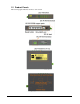
2.4 Din-Rail Mounting The steps to mount the switch on a Din-rail are: One Din-rail mounting bracket is provided in the product package as shown below: Install the bracket on the bottom of the switch unit. Mount the device on a Din-rail.
2.5 Panel Mounting One panel mounting bracket is provided in the product package as shown below: Install the bracket on the bottom of the switch unit.
2.6 Applying Power The switch provides two types of power interfaces, terminal block and DC power jack for receiving DC power input from external power supply system. Using Terminal Blocks Three terminal contacts are provided: Vdc Positive (+) terminal Vdc Negative (-) terminal Chassis ground ( Vdc : +5V ~ +30VDC) One 3P terminal plugs are provided together with the switch. The plug is shown below: Power wires : 24 ~ 12AWG (IEC 0.5~2.5mm2) Install the power source wires with the plug properly.
Using DC Power Jack When an external power system is not available, the switch provides a DC jack to receive power from typical AC-DC power adapter alternatively. AC Power Adapters: Optional commercial rated adapters are available for purchasing. AC input power: AC power voltage of your area, options Rated AC120V/60Hz DC7.5V 1A Rated AC230V/50Hz DC7.5V 1A Rated AC100V/50-60Hz DC7.5V 1A Rated AC100V/50-60Hz DC5V 1A Rated AC240V/50Hz DC7.
2.8 Making UTP Connections The 10/100/1000 copper ports support the following connection types and distances: Network Cables 10BASE-T: 2-pair UTP Cat. 3,4,5 , EIA/TIA-568B 100-ohm 100BASE-TX: 2-pair UTP Cat. 5, EIA/TIA-568B 100-ohm 1000BASE-T: 4-pair UTP Cat. 5 or higher (Cat.
2.9 Making Fiber Connection The mini-GBIC (SFP) port must be installed with an SFP fiber transceiver for making fiber connection. Your switch may come with an SFP transceiver pre-installed when it is shipped. Installing SFP Fiber Transceiver To install an SFP fiber transceiver into mini-GBIC port, the steps are: 1. Turn off the power to the switch. 2. Insert the SFP fiber transceiver into the mini-GBIC port. Normally, a bail is provided for every SFP transceiver. Hold the bail and make insertion. 3.
2.10 LED Indication LED Function State Interpretation POWER Power status ON OFF The power is supplied to the switch. The power is not supplied to the switch. LNK/1000M/ACT Port link status ON A 1000M link is established. (No traffic) BLINK Port link is up and there is traffic. OFF Port link is down. LNK/100M/ACT Port link status ON A 100M link is established. (No traffic) BLINK Port link is up and there is traffic. OFF Port link is down.
3. Advanced Functions To help a better understanding about the software management interfaces, this chapter describes some advanced functions provided by the switch. 3.1 Abbreviation Ingress Port : Ingress port is the input port on which a packet is received. Egress Port : Egress port is the output port from which a packet is sent out. IEEE 802.1Q Packets : A packet which is embedded with a VLAN Tag field VLAN Tag : In IEEE 802.
3.2 QoS Function The switch provides a powerful Quality of Service (QoS) function to guide the packet forwarding in four priority classes. The versatile classification methods can meet most of the application needs.
3.2.1 Packet Priority Classification Each received packet is examined and classified into one of four priority classes, Class 3, Class 2, Class 1 and Class 0 upon reception. The switch provides the following classification methods: 802.1p classification : use User Priority tag value in the received IEEE 802.1Q packet to map to one priority class DSCP classification : use DSCP value in the received IP packet to map to one priority class Port-based classification : used when 802.
3.3 VLAN Function The switch supports port-based VLAN, 802.1Q Tag VLAN and eight VLAN groups. 3.3.1 VLAN Operation The following figure illustrates the basic VLAN operation flow beginning from a packet received on an ingress port until it is transmitted from an egress port. The following sections describe the VLAN processes and Advanced VLAN mode settings provided by the switch. A global setting means the setting is applied to all ports of the switch.
3.3.2.3 Drop Untag Per Port Setting Enable - All untagged packets and priority-tagged packets are dropped. A priority-tagged packet is treated as an untagged packet in this switch. Only VLAN-tagged packets are admitted. Disable - Disable Untagged packet filtering 3.3.2.4 Drop Tag Per Port Setting Enable - All VLAN-tagged packets are dropped. A priority-tagged packet is treated as an untagged packet in this switch. Only untagged packets are admitted. Disable - Disable VLAN-tagged packet filtering 3.
3.3.5 VLAN Group Table Configuration The switch provides a table of eight VLAN groups to support up to eight VLANs at the same time. Each VLAN group is associated to one unique VLAN. The table is referred for VLAN classification.
3.3.8 Egress Tagging Rules Egress Tagging rules are used to make change to the packet before it is stored into egress queue of an egress port. Three egress settings are provided for each port and are described as follows: 3.3.8.1 Egress Settings Insert Tag (per port setting) Enable Insert the Tag data of the associated Packet Tag information into the packet Disable - No tagging is performed.
3.4 802.1X Authentication Port Access Control For some IEEE 802 LAN environments, it is desirable to restrict access to the services offered by the LAN to those users and devices that are permitted to make use of those services. IEEE 802.
4. Web Management The switch features an http server which can serve the management requests coming from any web browser software over TCP/IP network. Web Browser Compatible web browser software with JAVA script support Microsoft Internet Explorer 4.0 or later Netscape Communicator 4.x or later Set IP Address for the System Unit Before the switch can be managed from a web browser software, make sure a unique IP address is configured for the switch. 4.
4.3 Main Management Menu The following information describes the basic functions of the main menu. Configuration System Switch information, system and IP related settings Ports Port link status, port operation mode configuration VLAN VLAN related configuration QoS Quality of Service related configuration Port Mirroring Port mirroring related configuration 802.1X 802.
4.4 System Configuration Description MAC Address The MAC address factory configured for the switch It can not be changed in any cases.
4.4.1 Management VLAN Management VLAN settings allow administrator to access the switch and perform the switch management over a dedicated VLAN. The following rules are applied with the Management VLAN: 1. If the VLAN function is disabled, Management VLAN settings are ignored and no VLAN limitation is applied in accessing the switch web management interface. The switch web (http) server only accepts untagged management packets and replies untagged packets to the management host. 2.
4.
4.6 VLANs VLAN Configuration Description VLAN Disable Select to disable VLAN function All ports are allowed to communicate with each others freely with no VLAN limitation.
4.6.1 Port-based VLAN Mode Configuration Description Group 1, 2 Port-based VLAN group number Member ports Select member ports for the group [Apply] Click to apply the configuration change [Refresh] Click to refresh current configuration [Back] Click to go back to upper menu Operation in this mode: 1. The member ports of two groups are allowed to overlap. 2. The member ports in same group can communicate with other members only. 3. No packet tag is examined. 4.
4.6.
4.6.
4.6.3.
4.6.3.
4.6.3.
4.6.3.4 VLAN Groups Configuration Description Group Group number VID VID of the VLAN to which this group is associated 1 ~ 4095 - decimal 12-bit VID value Member Ports Select the admitted egress ports for the packets belong to the VLAN Port 1 ~ 6 - click to select Source Port Check Check whether the ingress port is the member port of the VLAN Enable - set to enable this check, the packet is dropped if ingress port is not member port of the VLAN.
4.6.4 Important Notes for VLAN Configuration Some considerations should be checked in configuring VLAN settings: 1. Switch VLAN Mode selection It is suggested to evaluate your VLAN application first and plan your VLAN configuration carefully before applying it. Any incorrect setting might cause network problem. 2. Double Tagged in Advanced VLAN Mode For a received packet, Ingress port [Keep Tag] setting and Egress port [Insert Tag] setting are enabled at the same time.
4.7 Quality of Service QoS Configuration Description Port Port number 802.1p 802.1p priority classification Enable - set to enable this classification to the port for priority-tagged and VLAN-tagged packets Disable - 802.
4.7.1 802.1p Mapping Configuration Description Port n Port number n tag m 3-bit User priority tag value m ( range : 0 ~ 7 ) Priority class Mapped priority class for tag m on Port n Class 3 ~ Class 0 [Apply] Click to apply the configuration change [Refresh] Click to refresh current configuration [Back] Click to go back to upper menu Every ingress port has its own 802.1p mapping table. The table is referred in 802.1p priority classification for the received packet.
4.7.
4.7.
4.8 Port Mirroring Configuration Description Sniffer Port The port is forwarded all packets received on the mirrored ports Mirrored Ports Select the ports which will be mirrored all received packets to the sniffer port.
4.9 802.1X Configuration Configuration Description Mode Disabled - disable 802.1x function Enabled - enable 802.1x function RADIUS IP IP address of the Radius server RADIUS UDP Port The UDP port for authentication requests to the specified Radius server RADIUS Secret The encryption key for use during authentication sessions with the Radius server. It must match the key used on the Radius server. Port Port number Admin State Port 802.
[Re-authenticate] Click to perform a manual authentication for the port [Force Reinitialize] Click to perform an 802.1x initialization for the port [Re-authenticate All] Click to perform manual authentication for all ports [Force Reinitialize All] Click to perform 802.1x initialization for all ports [Parameters] Click to configure Re-authentication parameters [Apply] Click to apply the configuration change [Refresh] Click to refresh current configuration 4.9.1 802.
4.
4.11 Reboot System This menu is used to reboot the switch unit remotely with current configuration. Starting this menu will make your current http connection lost. You must rebuild the connection to perform any management operation to the unit. 4.12 Restore Default This menu is used to restore all settings of the switch unit with factory default values. Note that this menu might change the current IP address of the switch and make your current http connection lost. 4.
4.13.2 Upload Configuration File Enter the path and file name of a configuration file for uploading. Configuration Description Filename Path and filename (configuration) [Browse] Click to browse your computer file system for the configuration file [Upload] Click to start upload [Backup Config File] Right click to download configuration file from the switch 4.13.3 Backup Configuration File The steps to download the configuration from the switch unit and save it on PC: 1.
Appendix. Factory Default Settings System Configuration Management VLAN - VID 0 Management VLAN - CFI 0 Management VLAN - User priority 0 IP Address 192.168.0.2 IP Subnet mask 255.255.255.0 Gateway IP 192.168.0.
VLAN Group 1 - VID 1 VLAN Group 1 - Member Ports Port 1, 2, 3, 4, 5, 6 VLAN Group 1 - Source Port Check Disable VLAN Group 2 - VID 2 VLAN Group 2 - Member Ports None VLAN Group 2 - Source Port Check Disable VLAN Group 3 - VID 3 VLAN Group 3 - Member Ports None VLAN Group 3 - Source Port Check Disable VLAN Group 4 - VID 4 VLAN Group 4 - Member Ports None VLAN Group 4 - Source Port Check Disable VLAN Group 5 - VID 5 VLAN Group 5 - Member Ports None VLAN Group 5 - Source Port Check Disable
Port 1~Port 6 - tag 5 Class 2 Port 1~Port 6 - tag 6 Class 3 Port 1~Port 6 - tag 7 Class 3 QoS DSCP Mapping DSCP 1 / Priority 0, Class 0 DSCP 2 / Priority 0, Class 0 DSCP 3 / Priority 0, Class 0 DSCP 4 / Priority 0, Class 0 DSCP 5 / Priority 0, Class 0 DSCP 6 / Priority 0, Class 0 DSCP 7 / Priority 0, Class 0 All others DSCP Class 0 QoS Service Policy Port 1 Strict priority Port 2 Strict priority Port 3 Strict priority Port 4 Strict priority Port 5 Strict priority Port 6 Stri