Installation Guide 24-port 10/100 Fast Ethernet Switch with 1 Fiber Connection Model Name : KS-324F
We make no warranties with respect to this documentation and disclaim any implied warranties of merchantability, quality, or fitness for any particular purpose. The information in this document is subject to change without notice. We reserve the right to make revisions to this publication without obligation to notify any person or entity of any such changes. Trademarks or brand names mentioned herein are trademarks or registered trademarks of their respective companies.
Contents 1. Introduction 1.1 Package Contents 2. Where to Place the 24port Switch 3. Configure The Network Connection 3.1 Connecting Devices to the 24port Switch 3.2 Connecting to Another Ethernet Switch/Hub 3.3 Application 4. For 100BaseFX Connection 4.1 Adding 100BaseFX Module 5. LED Conditions Definition 5.1 LEDs Defined 6. Configure from Console 6.1 Hardware Setting for console 6.
1. Introduction This 24port Switch is a 24-port 10/100Mbps Fast Ethernet switch. This switch supports the advanced features for current switch design. This switch can auto detect the 10/100Mbps speed, full/half duplex mode and MDI/MDI-X connection. These features provide user the simplest way to complete the network connection. There is a console port on the switch. You can configure the switch from the console for VLAN setting, port setting and priority setting.
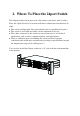
2. Where To Place the 24port Switch This 24port Switch can be placed on a flat surface (your desk, shelf or table). Place the 24port Switch at a location with these connection considerations in mind: l l l l The switch configuration does not break the rules as specified in Section 3. The switch is accessible and cables can be connected easily to it. The cables connected to the switch are away from sources of electrical interference such as radio, computer monitor, and light fixtures.
3. Configure the Network Connection 3.
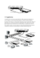
Max. 100m (328 feet) ) TO: MDI or MDI-X port 3.3 Application A switch can be used to overcome the hub to hub connectivity limitations as well as improve overall network performance. Switches make intelligent decisions about where to send network traffic based on the destination address of the packet. As a result, the switch can significantly reduce unnecessary traffic. The example below demonstrates the switch ability to segment the network.
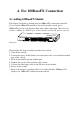
4. For 100BaseFX Connection 4.1 Adding 100BaseFX Module This 24port switch has a module port for 100BaseFX connection extension. You can add a 100BaseFX module to the switch and this switch gets a 100BaseFX port for long distance fiber optic cable connection. But when this module is added, the 24th TP port will be disable and this FX port become the Module Port 24th port. Please follow the steps to add the module to the switch. 1. Turn off the switch. 2.
5. LEDs Conditions Definition 5.1 LEDs Defined The LEDs provide useful information about the switch and the status of all individual ports. LED STATUS CONDITION Power ON Switch is receiving power. Link / Act ON Port has established a valid link. Flashing Data packets being received or sent. Green The connection speed is 100Mbps. Yellow The connection speed is 10Mbps. ON The connection is Full Duplex. Flashing Packet collisions occurring.
6. Configure from Console 6.1 Hardware Setting for Console Before using the console connection to configure the switch, please make sure that you have already install the terminal program "HyperTrm" in your Windows. If you can not find it in your Windows, please install it first with your Windows Installation Disk. You can also use other terminal program for console setting if you already have one. 1.
disable the backpressure function for half duplex. If it is enable, it can prevent packets lost in half duplex mode. But it will also reject packets when the network traffic is very heavy and that may cause some network connections fail. 2. Port Setting : You can set the operation speed, duplex mode from here. If "Auto_Negotiation" is enable, the settings in speed and duplex will be ignored. If "Auto_Negotiation" is disable, the speed and duplex setting will take effect. 3.
You can configure VLAN groups from this function. Because every port must belong to some VLAN, the removed port from VLAN will be assigned to Group 24 automatically if it does not belong to any VLAN any more after being removed. In the setting, VLAN groups can be overlapped on ports in this switch. 4. Priority Setting : There are two transmit priority queues for each port of the switch and you can configure the priority setting here.
A. Product Specifications Access Method Standards Conformance Communication Rate Communication Mode Media Supported Indicator Panel Number of Ports Console MDI-X/MDI Selection Dimensions Certification Emissions Immunity Power Consumption Input Power Temperature Humidity CSMA/CD, 10 Mbps or 100 Mbps IEEE 802.3 10BASE -T, IEEE 802.
B.
C. Compliances EMI Certification FCC Class A Certification (USA) Warning: This equipment generates, uses, and can radiate radio frequency energy and, if not installed and used in accordance with the instruction manual, may cause interference to radio communications.
D. Warranty We warrant to the original owner that the product delivered in this package will be free from defects in material and workmanship for a period of warranty time from the date of purchase from us or the authorized reseller. The warranty does not cover the product if it is damaged in the process of being installed. We recommend that you have the company from whom you purchased this product install it.