0/100 Managed Fast Ethernet Switch with 100FX and Gigabit Connectivity KS-2260 Optional 100FX Modules Optional Gigabit Modules Operation Manual DOC.
(C) 2002 KTI Networks Inc. All rights reserved. No part of this documentation may be reproduced in any form or by any means or used to make any directive work (such as translation or transformation) without permission from KTI Networks Inc. KTI Networks Inc. reserves the right to revise this documentation and to make changes in content from time to time without obligation on the part of KTI Networks Inc. to provide notification of such revision or change.
The information contained in this document is subject to change without prior notice. Copyright (C) KTI. All Rights Reserved. TRADEMARKS Ethernet is a registered trademark of Xerox Corp. WARNING: This equipment has been tested and found to comply with the limits for a Class A digital device, pursuant to Part 15 of the FCC Rules. These limits are designed to provide reasonable protection against harmful interference when the equipment is operated in a commercial environment.
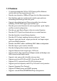
Table of Contents 1. Introduction ................................................................ 8 1.1 Introduction .................................................................................... 8 1.2 Features ........................................................................................ 9 1.3 Hardware Specifications ............................................................. 10 1.4 Software Specifications ............................................................... 12 1.4.
3.2 Switch Static Configuration ......................................................... 46 3.2.1 Port Configuration .................................................................... 47 3.3.2 Trunk Configuration .................................................................. 49 3.3.3 VLAN Configuration .................................................................. 50 3.3.3.1 VLAN Configure ..................................................................... 50 3.3.3.2 Create a VLAN Group .......
3.4.6 802.1X ....................................................................................... 3.4.6.1 Enable 802.1X Protocol ......................................................... 3.4.6.2 802.1X System Configuration ............................................... 3.4.6.3 802.1X Per Port Configuration .............................................. 3.4.6.4 802.1X Misc. Configuration ................................................... 3.5 Status and Counters ..........................................
5.5.6.1 IGMP Snooping .................................................................... 121 5.5.6.2 Static MAC Address ............................................................. 122 5.5.6.3 MAC Address Filtering ......................................................... 123 5.5.7 VLAN configuration ................................................................. 124 5.5.7.1 Port-based VLAN ................................................................. 125 5.5.7.2 802.1Q VLAN .......................
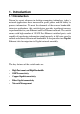
1. Introduction 1.1 Introduction Driven by recent advances in desktop computing technology, today’s network applications have increased in speed, power and the ability to process information. To meet the demands of these more bandwidthintensive applications, this switch device provides significant increase in performance for your Ethernet and Fast Ethernet network.
1.2 Features • • • • • • • • • • • • • • • • • • • • • • 19-inch rack mountable 24-Port 10/100 managed Fast Ethernet switch with two Giga expansion port slots Provides two alternative 100Base-FX port slots for fiber connections Non-blocking and store-and-forward switch engine performs forwarding and filtering at full wire speed.
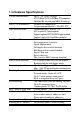
1.3 Hardware Specifications 10/100 Switched Ports Port 23, 24 Alternatives Giga Switched Ports Port Control Function Flow Control Methods Forwarding speed Trunking Function Port Sniffering MAC address aging time MAC Address Table Broadcast Storm Filtering Filtering MAC Address Port 1 ~ 24, Total : 24 ports 802.3 10Base-T, 802.3u 100Base-TX compliant Shielded RJ-45 with auto MDI-X function 100Base-FX connectivity 2 expansion module slots - Slot F23, F24 2 expansion Slots - Slot G1, G2 802.3z and 802.
Network Access Control Function 802.1X protocol support for all ports Radius client configuration Per port mode - Auto, Fu, Fa, No QoS Function 2-level (High/Low) priority for Tx queues Selectable Tx High/Low service ratio Priority Decision Method First - Port-based priority Second - 802.1p priority (Tag priority value) VLAN Function Mode options if enabled Port-based VLAN 802.1Q Tag-based VLAN Port-based VLAN Max. 26 VLAN groups VLAN-tagging is ignored No tag modification for tagged packets 802.
1.
1.4.1 Management Objects List of management objects supported by console and Telnet interfaces : Management Objects Console Telnet Web SNMP Boot diagnostics Yes Login check Yes Yes Yes Port configuration Yes Yes Yes Trunk configuration (& LACP) Yes Yes Yes VLAN configuration Yes Yes Yes QoS Priority configuration Yes Yes Yes MAC address aging setting Yes Yes Yes Broadcast storm filtering setting Yes Yes Yes Max.
Management Objects Console Telnet Web SNMP Port state - enable/disable Yes Yes Yes Yes Port status - link, speed Yes Yes Yes Yes Port static counters Yes Yes Yes Yes Device Mac address information Yes Yes Yes Yes System firmware version information Yes Yes Yes System hardware version information Yes Yes Yes System default configuration version Yes Yes Yes G1, G2 module information Yes Yes Yes Yes F23, F24 module information Yes Yes Yes Yes Cooling Fan1 Fan2 status Yes Yes Yes Yes LACP status Yes Yes Yes IGM
1.5 Function Descriptions 1.5.1 LACP Trunking Function The switch provides a trunking function, which is compliant with 802.3ad standard. 802.3ad is a specification from IEEE that allows us to bundle several physical port links together to form one logical port , called a trunk between two devices. It supports Link Aggregation Control Protocol (LACP). IEEE 802.3ad trunking also allows redundant connections between devices to be combined for more aggregate bandwidth between devices supporting LACP.
same time. Those member ports which are not work ports are standby to become work port if any current work port fails to operate. This transition takes about 30 seconds. Each member port can be set LACP Passive or LACP active as described below: LACP Passive : The port does not initiate the LACP negotiation, but it does understand the LACP packet. It will reply to the received LACP packet to eventually form the link aggregation if its link partner is requesting to do so (in active state).
1.5.2 IP Multicast Function Internet Protocol (IP) multicast is a bandwidth-conserving technology that reduces traffic by simultaneously delivering a single stream of information to thousands of corporate recipients and homes. Applications that take advantage of multicast include video conference, corporate communications, distance learning, and distribution of software, stock quotes, and news.
IGMP Internet Group Management Protocol (IGMP) is used to dynamically register individual hosts in a multicast group on a particular LAN. Hosts identify group memberships by sending IGMP messages to their local multicast router. Under IGMP, routers listen to IGMP messages and periodically send out queries to discover which groups are active or inactive on a particular subnet. RFC 2236 defines the specification for IGMP Version 2.
IGMP Snooping IGMP snooping requires the LAN switch to examine, or snoop, some Layer 3 information in the IGMP packets sent between the hosts and the router. When the switch hears the IGMP host report from a host for a particular multicast group, the switch adds the host's port number to the associated multicast table entry. When the switch hears the IGMP leave group message from a host, it removes the host's port from the table entry.
1.5.4 Static MAC Address The switch provides Static MAC Address setup function. The static MAC addresses are the MAC addresses which are setup by LAN administrators and are not learned by the switch automatically. The static addresses are stored and referred in switch MAC address table permanently regardless of whether the MAC addresses are physically disconnected to the switch.
1.5.6 VLAN Function Virtual LANs (VLANs) can be viewed as a group of devices on different physical LAN segments which can communicate with each other as if they were all on the same physical LAN segment. It can create a network that is independent of physical location and group users into logical workgroups.
1.5.6.2 IEEE 802.1Q VLAN (Tag-based VLAN) Tag-based VLAN is an IEEE 802.1Q specification standard. Therefore, it is possible to create a VLAN across devices from different venders. IEEE 802.1Q VLAN uses a technique to insert a tag into the Ethernet frames. Tag contains a VLAN Identifier (VID) that indicates the VLAN numbers. The switch can classify each received packet as belonging to one and only one VLAN.
1.5.6.3 Protocol-based VLAN In order for an end station to send packets to different VLANs, it itself has to be either capable of tagging packets it sends with VLAN tags or attached to a VLAN-aware bridge that is capable of classifying and tagging the packet with different VLAN ID based on not only default PVID but also other information about the packet, such as the protocol. The switch can support 802.
re-configures the spanning-tree topology and reestablishes the link by activating the standby path. Spanning-Tree Protocol operation is transparent to end stations, which are unaware whether they are connected to a single LAN segment or a switched LAN of multiple segments. STP related parameters Priority : A value to identify the root bridge. The bridge with the lowest value has the highest priority and is selected as the root.
Learning : The switch enters the Learning State if no path with a higher priority is found during the Listening State. Learned entries are entered in the Unicast Destination Forwarding Table. Normal data is not transmitted. Forwarding : The switch enters the Forwarding State after having been in the Learning State for a predefined time period. Normal data is transmitted. Per port control settings PathCost : Specifies the path cost for each port.
1.5.9 QoS Priority Function This switch supports two priority levels, high and low, and provides two priority functions: 1. Port-based Priority (Static priority) 2. 802.1p Priority (VLAN tagged priority) Priority Classification Methods Static priority is called port-based priority. The priority level of a receiving packet is determined by the configured priority of the input port where the packet is received and the content of the packet is ignored.
1.5.10 802.1X Port-Based Network Access Control For some IEEE 802 LAN environments, it is desirable to restrict access to the services offered by the LAN to those users and devices that are permitted to make use of those services. IEEE 802.
The 802.1X authenticator operates as a go-between with the supplicant and the authentication server to provide services to the network. When a switch is configured as an authenticator, the ports of the switch must then be configured for authorization. In an authenticator-initiated port authorization, a client is powered up or plugs into the port, and the authenticator port sends an Extensible Authentication Protocol (EAP) PDU to the supplicant requesting the identification of the supplicant.
Enable 802.1X protocol Radius client configuration Radius server IP : IP address of the Radius server Shared key : en encryption key for use during authentication sessions with the specified Radius server. It must match the key used on the Radius server.
2. Installation and Management 2.1 Panel Description 2.2 AC Power Supply One AC power cord which meets the specification of your country of origin was supplied with the switch unit. Before installing AC power cord to the switch, make sure the AC power switch is in OFF position and the AC power to the power cord is turned off.
2.3 Network Switched Ports The switch provides three types of switched ports as follows: Port Number Label Specifications Port Type Modules Port 1 - 22 1 - 22 Fixed RJ-45 10/100TX No Port 23 - 24 23 - 24 Fixed RJ-45 10/100TX No F23 - F24 Module slot 100FX Optional Port 25-26 G1 - G2 Module slot Gigabit Optional 2.3.1 10/100TX Ports The 10/100TX ports supports the following connection types and distances: Speed Compliance 10Mbps IEEE 802.3 10BASE-T 100Mbps IEEE 802.3u 100BASE-TX Cables Cat.
2.3.2 100FX Modules Port 23 and Port 24 also provide optional fiber connectivity. The following installation rules should be applied: 100FX Module Installation F23 Slot F24 Slot None None Installed None None Installed Installed Installed Working Connectors Port 23 Port 24 P23 RJ-45 P24 RJ-45 F23 module P24 RJ-45 can not be used P23 RJ-45 F24 module F23 module F24 module This figure illustrates an example of 100FX module. Every module has one jumper JP1 as shown.
The following 100FX modules are supported by F23 and F24 slots: Part Number 2260-FMT 2260-FMC 2260-FJM 2260-FVM 2260-FSA2 Connector Duplex ST Duplex SC MT-RJ VF-45 Duplex SC Cable MMF* MMF MMF MMF SMF* Distance 2 km 2 km 2 km 2 km 20 km Note: * MMF - Multimode Fiber cable 50/125, 62.5/125 mm * SMF - Single Mode Fiber cable 8.7/125, 9/125, 10/125 mm Specifications IEEE 802.
2.3.3 Gigabit Ports and Modules Port 25 and Port 26, labeled G1 and G2 respectively, support the following Gigabit modules: Part Number Connector 2260-GT RJ-45 2260-SXC Duplex SC 2260-SXL Duplex LC 2260-LXC Duplex SC Cable Cat.5e MMF 62.5/125mm MMF 50/125mm MMF 62.5/125mm MMF 50/125mm MMF 62.
Specifications Part Number Compliance 2260-GT IEEE 802.3ab 1000BASE-T IEEE 802.3u 100BASE-TX IEEE 802.3 10BASE-T Auto-negotiation function MDI-X RJ45 2260-SXC IEEE 802.3z 1000BASE-SX 2260-SXL IEEE 802.3z 1000BASE-SX 2260-LXC IEEE 802.3z 1000BASE-LX Optical Specifications Part Number Wavelength 2260-SXC 850nm 2260-SXL 850nm 2260-LXC 1310nm Speed 1000Mbps 100Mbps 10Mbps Duplex Half / Full Half / Full Half / Full 1000Mbps 1000Mbps 1000Mbps Full Full Full Output Power Input Optical Power -9.
2.4 Rack Mounting Two 19-inch rack mounting brackets are supplied with the switch for 19inch rack mounting. The steps to mount the switch onto a 19-inch rack are: 1. Turn the power to the switch off. 2. Install two brackets with supplied screws onto the switch as shown in above figure: 2. Mount the switch onto 19-inch rack with rack screws securely. 3. Turn the power to the switch on.
2.5 LED Indicators LED Name System LEDs P(Power) C(Console) D(Diag) State Interpretation On Off On Off Blink On Port 1 ~ Port 24 LEDs 100/10 On Off Link/Act. On Off Blink FDX/Col. On Off Blink Power is supplied to the unit. No power is supplied to the unit. Tx activities No Tx or Rx Diagnostic and initialization in process Diagnostic and initialization completed Port speed is 100Mbps. Port speed is 10Mbps. Port link up Port link down Port Tx/Rx activities Port is in full duplex. Port is in half duplex.
2.6 Cooling Fans The switch is equipped with two cooling fans. Both fans are featured with failure detection function. When the fan operation speed is below the specification, it is detected as a failure. The fan status can be monitored via management functions. One fan failure trap is also issued when fan failure event occurs. Important : Do not operate the switch unit when a fan failure is detected.
2.
2.7.1 Setup for Out-of-band (Console) Management Before doing any in-band management, it is necessary to perform console operation for configuring IP and SNMP related settings for the first time the switch is received for installation. Any PC running Windows 95/ 98/ or NT can be used as a console via COM port. Windows Hyper Terminal program is an ideal and the most popular software for such console terminal operations. To setup console operation, the steps are: 1.
2.7.2 Setup for In-band Management To perform an in-band management, it is necessary to connect the system to your TCP/IP network. The steps are: 1. Configure IP and SNMP related settings to the device using direct console management when you receive it first time for the installation. 2. Find a proper straight-through Category 5 UTP cable (maximal length 100 meters) for the connection. 3.
3. Console and Telnet Operation This chapter describes the detailed console operation. It can be applied to either out-of-band console management or in-band Telnet management. Refer to Chapter 2 for installation details. Cold Start When the power to the switch is turned on, the device start initialization and self-test process. The self-test messages are displayed as follows if a console connection is established successfully.
Direct Console Management When you can see the self-test messages shown on screen properly, you can press key to start console login operation. Go to Login Prompt section in next page directly. Telnet Management Use Telnet software to perform the management operation. The most convenient solution is using the built-in Telnet function in a Windows 95/98/ or NT PC. Enter into DOS window and invoke Telnet command : >telnet xxx.xxx.xxx.xxx to connect to the device. The specified xxx.xxx.xxx.
3.1 Main Menu When login successfully, the main menu is shown as follows: --------------------------------------------Main Menu Switch Static Configuration Protocol Related Configuration Status and Counters Reboot Switch TFTP Update Firmware Logout Configure the switch.
The following operation convention is commonly used for later configuration pages: Action menu: Exit configuration Edit each configuration value Save all configured values Browse previous configuration page Browse next configuration page Control keys for action menu: [Tab] key [Backspace] key [Enter] key Move to next item Move to previous item Confirm selection Control keys used for operation: [Tab] key [Backspace] key [Space] key [Ctrl+A] key Mov
3.
3.2.
Port : Port number Display names - PORT1 - PORT24, G1 - G2 Type : Port type Display names - 100Tx, 100FX, 1000T, 1000FX InRate : Input (Ingress) rate control setting, 100Kbytes per unit.
3.3.
3.3.3 VLAN Configuration ---------------------------------------------------Managed 24+2G Switch : VLAN Configuration VLAN Configure Create a VLAN Group Edit/Delete a VLAN Group Group Sorted Mode Previous Menu Configure the VLAN pvid and ingress.egress rules Tab=Next Item BackSpace=Previous Item Quit=Previous Menu Enter= Select Item ------------------------------------------------------------------------- 3.3.3.
If 802.1Q mode is selected, some additional settings are required as follows: ---------------------------------------------------Managed 24+2G Switch : VLAN Support Configuration VLAN Mode : 802.
3.3.3.
Create an 802.
Member : Give a member setting, Options UnTagged : the specified port is a member port and outgoing frames are not tagged. Tagged : the specified port is a member port and outgoing frames are tagged. No : the specified port is not a member port Note: If more than two VLAN groups are configured with same protocol value, make sure the member ports of those groups are not overlapping. 3.3.3.
Example to edit Vlan2 group: ---------------------------------------------------Edit a VLAN Group VLAN Name: [Vlan2 ] VLAN ID:[2 ](1~4094) Protocol VLAN : AppleTalk/NetBIOS Port Member ----------------------PORT1 UnTagged PORT2 Tagged PORT3 UnTagged PORT4 No PORT5 No PORT6 No PORT7 No PORT8 No action-> -----------------------------------------------------------------Tab=Next Item BackSpace=Previous Item Quit=Previous Menu Enter= Sele
3.3.4 Misc Configuration ---------------------------------------------------Managed 24+2G Switch : Misc Configuration MAC Age Interval Broadcast Storm Filtering Max bridge transmit delay bound Port Security Collision Retry Forever Hash Algorithm Previous Menu Configure the MAC aging time Tab=Next Item BackSpace=Previous Item Quit=Previous Menu Enter= Select Item ------------------------------------------------------------------------- 3.3.4.
3.3.4.
3.3.4.3 Max Bridge Transmit Delay Bound ---------------------------------------------------Managed 24+2G Switch : Max Bridge Transmit Delay Bound Max bridge transmit delay bound : OFF Low Queue Delay Bound : ENABLE Low Queue Max Delay Time : 255 action-> (2ms/unit) ------------------------------------------------------------------------- Max bridge transmit delay bound: Limit the packets queuing time in switch.
3.3.4.
3.3.4.5 Collision Retry Forever ---------------------------------------------------Managed 24+2G Switch : Collision Retry Forever Collision Retry Forever : Enabled action-> ---------------------------------------------------- Collision Retry control setting for half duplex mode : Options - Enabled = collision retry forever Disabled = collision retry 48 times then drop frames 3.3.4.
3.3.5 Administration Configuration ---------------------------------------------------Managed 24+2G Switch : Device Configuration Change Username Change Password Device Information IP Configuration Previous Menu ---------------------------------------------------- 3.3.5.
3.3.5.2 Change Password ---------------------------------------------------Managed 24+2G Switch : Password Configuration Old Password : xxxx New Password : xxxx enter again : xxxx action-> ---------------------------------------------------- The password is used together with UserName for login operation. 3.3.5.
3.3.5.4 IP Configuration ---------------------------------------------------Managed 24+2G Switch : Device Configuration DHCP : Disabled IP Address : 192.168.0.2 Subnet Mask : 255.255.255.0 Gateway action-> : 192.168.0.
3.3.
3.3.7 Priority Configuration ---------------------------------------------------Managed 24+2G Switch : The Priority Configuration Port Static Priority 802.1p Priority Previous Menu ---------------------------------------------------- Two priority methods are provided: • Port Static Priority (Port-based Priority) • 802.1p Priority Note: The switch uses the following rules: 1. Applies Static Priority method first for tagged or untagged packets. 2. If port static priority is disabled, applies 802.
3.3.7.1 Static Priority ---------------------------------------------------Managed 24+2G Switch : Port Priority Port Priority ---------------------PORT1 Low PORT2 Low PORT3 High PORT4 High PORT5 Disable PORT6 Disable PORT7 Disable PORT8 Disable action-> ---------------------------------------------------- Specify the static priority level for each port. The options are: Disable : Port priority is disabled. 802.
3.3.7.2 802.1p Priority ---------------------------------------------------Managed 24+2G Switch : 802.1p Priority Configuration Priority 0 LOW Priority 1 LOW Priority 2 LOW Priority 3 LOW Priority 4 HIGH Priority 5 HIGH Priority 6 HIGH Priority 7 HIGH QoSMode First Come First Service action-> : ---------------------------------------------------- Priority 0 ~ 7 : Packet priority value map to high or low level.
3.3.8 MAC Address Configuration ---------------------------------------------------Managed 24+2G Switch : MAC Address Configuration Static MAC Address Filtering MAC Address Previous Menu ---------------------------------------------------- 3.3.8.
Add static MAC address ---------------------------------------------------Managed 24+2G Switch : Add Static MAC Address MAC Address : 0040F6FE0005 Port Num : PORT3 Vlan ID : 2 action-> ---------------------------------------------------- MAC Address : the Ethernet MAC address Port Num : press key to select the port number Vlan ID : If tag-based (802.1Q) VLAN is enabled on the switch, each static address is associated with one VLAN.
3.3.8.2 Filtering MAC Address Refer to Chapter 1 for description of MAC address filtering function. The operations to Add/Edit/Delete a filter MAC address are similar to the operations for static MAC address table.
3.4 Protocol Related Configuration ---------------------------------------------------Managed 24+2G Switch : The Protocol Related Configuration STP SNMP GVRP IGMP LACP 802.1x Previous Menu ---------------------------------------------------- 3.4.
STP Enable ---------------------------------------------------Managed 24+2G Switch : STP Enabled/Disabled Configuration STP action-> : Enabled ---------------------------------------------------- Spanning Tree function can be enabled or disabled. Press Space key to select enable or disable.
Current spanning tree information about the Root Bridge is shown on the left side and new values for STP parameters are configured on the right side. The settings are: Priority : The priority is assigned to the switch. The higher value is lower priority. Range: 0 - 65535 Max Age : The number of seconds a bridge waits without receiving Spanning Tree protocol configuration messages before attempting a reconfiguration. Valid value : 6 ~ 40.
Perport Configuration ---------------------------------------------------Managed 24+2G Switch : STP Port Configuration Port PortSate PathCost Priority --------------------------------------------PORT1 Forwarding 10 128 PORT2 Forwarding 10 128 PORT3 Forwarding 10 128 PORT4 Forwarding 10 128 PORT5 Forwarding 10 128 PORT6 Forwarding 10 128 PORT7 Forwarding 10 128 PORT8 Forwarding 10 128 action-> ------------------------------
3.4.2 SNMP ---------------------------------------------------Managed 24+2G Switch : SNMP Protocol System Options Community Strings Trap Managers Previous Menu ---------------------------------------------------- Use this page to setup SNMP related parameters and SNMP trap hosts related parameters. 3.4.2.1 System Options ---------------------------------------------------Managed 24+2G Switch : System Options Configuration System Name : .....................................................................
3.4.2.2 Community Strings ---------------------------------------------------Managed 24+2G Switch : SNMP Community Configuration Community Name Write Access --------------------------------------------public Restricted private Unrestricted action-> ---------------------------------------------------- This page shows current Community strings which are allowed to access MIB objects of the switch unit via SNMP management interface.
3.4.2.3 Trap Managers A trap manager is a management station that allows to receive SNMP traps. An SNMP trap is issued by the switch when the associated trap event occurs in the switch. A trap manager is defined by its IP address and a community string. Up to three trap managers can be configured.
3.4.3 GVRP This page you can enable or disable the GVRP (GARP VLAN Registration Protocol) support. ---------------------------------------------------Managed 24+2G Switch : GVRP Configuration GVRP : Enabled action-> ---------------------------------------------------- Options - Enabled, Disabled 3.4.4 IGMP This page you can enable or disable the IGMP support.
3.4.5 LACP This menu list is used to configure LACP trunk groups. ---------------------------------------------------Managed 24+2G Switch : LACP Configuration Working Ports Setting State Activity LACP Status Previous Menu ---------------------------------------------------- 3.4.5.
3.4.5.
3.4.5.3 LACP Status ---------------------------------------------------Managed 24+2G Switch : LACP Group Status Group Key : 1 Port_No : 1 2 3 4 action-> ---------------------------------------------------- This page shows LACP status of each trunk group. 3.4.6 802.1X ---------------------------------------------------Managed 24+2G Switch : 802.1x protocol 802.
3.4.6.1 Enable 802.1X Protocol ---------------------------------------------------Managed 24+2G Switch : 802.1x Enabled/Disabled Configuration 802.1x action-> : Enabled ---------------------------------------------------- This menu is used to enable 802.1X function of the switch. 3.4.6.2 802.1X System Configuration ---------------------------------------------------Managed 24+2G Switch : 802.1x System Configuration Radius Server IP : xxx.xxx.xxx.
3.4.6.3 802.1X Per Port Configuration ---------------------------------------------------Managed 24+2G Switch : 802.1x Port Status (Force Unauth= Fu, Force Au=Fa, Auto=Au, None=No) Port Status ------------------PORT1 No PORT2 No PORT3 No PORT4 No PORT5 No PORT6 No PORT7 No PORT8 No action-> ---------------------------------------------------- This menu is used to configure per-port 802.1x mode.
3.4.6.4 802.1X Misc. Configuration ---------------------------------------------------Managed 24+2G Switch : 802.1x Misc Configuration Quiet-period <0..65535, default=60> : 60 Tx-period <0..65535, default=30> : 30 Supplicant-timeout <0..300, default=30> : 30 Server-timeout <0..300, default=30> : 30 ReAuthMax <1..10, default=2> : 2 Reau-period <0..9999999, default=3600> : 3600 action-> ---------------------------------------------------- This menu is used to setup 802.
3.5 Status and Counters ---------------------------------------------------Managed 24+2G Switch : Status and Counters Port Status Port Counters System Information Previous Menu ---------------------------------------------------- Menu functions: Port Status : display the status of all switched ports and trunk groups. Port Counters : display the statistic counters of each ports. System Information : display system related information, cooling fan status, and all slot module status.
3.5.
3.5.
3.5.3 System Information ---------------------------------------------------Managed 24+2G Switch : System Information MAC Address : 0040F6FE0005 Firmware version : x.x ASIC version : x.xx PCBA version : x.
3.6 Reboot Switch ---------------------------------------------------Managed 24+2G Switch : Restart Configuration Restart Default Previous Menu ---------------------------------------------------- 3.6.1 Restart This command will reboot the switch with current configuration setting values. Confirmation prompt is: ---------------------------------------------------Rebooting device ..... Do you want to continue? (y/n) ---------------------------------------------------- 3.6.
3.
3.7.1 TFTP Update Firmware ---------------------------------------------------Managed 24+2G Switch : TFTP Update Firmware TFTP Server : 192.168.0.15 Remote File Name : image.bin action-> ---------------------------------------------------- The steps to use TFTP to update switch firmware are: 1. Start your TFTP server and place the image file of the new firmware on the TFTP server. 2.
3.7.2 TFTP Restore Configuration ---------------------------------------------------Managed 24+2G Switch :Restore Configuration File TFTP Server : 192.168.0.15 Remote File Name : data.dat action-> ---------------------------------------------------- The steps to use TFTP to restore switch configuration are: 1. Start your TFTP server and place the image file of new configuration file on the TFTP server. 2.
3.7.3 TFTP Backup Configuration ---------------------------------------------------Managed 24+2G Switch :Upload Configuration File TFTP Server : 192.168.0.15 Remote File Name : newdata.dat action-> ---------------------------------------------------- To use TFTP to upload current switch configuration and save it as a backup image file onto TFTP server. The steps are: 1. Start your TFTP server. 2.
4. SNMP Management SNMP management are performed at a network management station running SNMP network management application manager software. The following figure illustrates an example model: The switch unit serves as an SNMP agent and provides the capabilities that allows network administrators via SNMP protocol to set parameters and view switch status defined in the standard MIB-II and private MIB. A trap manager is a management station that allows to receive SNMP traps.
4.1 Configuring SNMP Settings via Console Operation Before performing SNMP operation, proper SNMP settings must be configured.
The following MIB-2 objects are related to the switched ports and are indexed by a port number 1 ~ 27 (27 = CPU port): Port MIB-2 Objects ifIndex.1 ~ 27 ifDescr.1 ~ 26 ifDescr.27 ifType.1 ~ 27 ifSpeed.1 ~ 24 ifSpeed.25 ~ 26 Set/Get Get Get Get Get Get Get ifSpeed.27 ifAdminStatus.1 ~ 27 Get Set ifAdminStatus.1 ~ 27 Get ifOperStatus.1 ~ 27 Get ifLastChange.1 ~ 27 ifInOctets.1 ~ 27 ifInUcastPkts.1 ~ 27 ifInNUcastPkts.1 ~ 27 ifInDiscards.1 ~ 27 ifInErrors.1 ~ 27 ifOutOctets.1 ~ 27 ifOutUcastPkts.
The following are device-related private MIB objects: Private MIB Objects DeviceName.0 PortNumber.0 F23_Module.0 Set/Get Get Get Get F23_Module.0 Get G1_Module.0 Get G2_Module.0 FanStatus1.0 Get Get FanStatus2.
4.3 SNMP Traps The switch supports the following SNMP traps. When the trap event occurs, the SNMP agent will generate a trap notification to SNMP trap manager stations. Up to three trap managers can be supported. Each trap manager must be configured with : IP address and Community string which the trap manager belongs.
5. Web Management The managed switch features an http server which can serve the management requests coming from any web browser software over internet or intranet network. Web Browser Microsoft Internet Explorer 5.0 or later Important: The switch does not support any version of Netscape browser software.
5.1 Start Browser Software and Making Connection Start your browser software and enter the IP address of the device unit to which you want to connect. The IP address is used as URL for the browser software to search the device. URL : http://xxx.xxx.xxx.xxx/ Factory default IP address : 192.168.0.2 Login the Username and Password to enter web management. Refer to Appendix A for factory default values.
5.2 Web Management Home Overview This page provides the following menu list. Each menu is described individually in the following sections.
5.3 Port status This page shows all port status in a scroll bar list.
Auto Negotiation : Display the auto negotiation mode setting and status Config / Atual Auto = enable auto negotiation with the specified highest capability Force = disable auto negotiation and use forced mode Nway-force = enable auto negotiation with the specified capability Note : Specified capability means speed and duplex configuration Speed status : Display port speed setting and status Config : port speed capability setting Atual : port speed is used currently Port 1-24 : 10/100Mbps G1 port, G2 port :
5.4 Port Statistics This page displays the function, link status, and statistic counters of all ports by a scroll list.
Click port icons on the switch image to also see a single port counters as follows: 5.
5.5.1 IP Address Available settings: DHCP : DHCP function setting Enable : enable DHCP client function to get dynamic IP address Disable : disable DHCP client function and use static IP address IP Address : Static IP address assigned to the managed switch unit Subnet_Mask : subnet mask setting Gateway : Default gateway IP address Click Buttons: [Apply] : confirm and apply the setting changes [Help] : description about the settings The switch unit must be reset to use the new IP parameters.
5.5.2 Switch Setting This menu provides the following functions: Basic : the basic information of the managed switch unit Module Info : the information of the Gigabit modules installed Advanced : some switch related settings 5.5.2.
5.5.2.
5.5.2.3 Advanced Miscellaneous settings : MAC Address Age-out Time : Type the number of seconds that an inactive MAC address remains in the switch address table. The valid range is 300~765 seconds (must be multiple of 3). Default is 300 seconds. Max bridge transmit delay bound control : Limit the packets queuing time in switch. If enabled and queuing time expired, the queued packets will be dropped.
Enable Low Queue Delay Bound : setting to limit the low priority packets queuing time in switch. If enabled and queuing time expired, the low priority packets queued in switch will be sent. Note: Make sure Max bridge transit delay bound control is enabled when Low Queue Delay Bound control is set to ENABLE. Max. Delay Time : max. low queuing time, value range 1 ~ 255 (2ms/unit) Broadcast Storm Filter Mode : To configure broadcast storm control, enable it and set the upper threshold applied to all ports.
Priority Queue Service settings (select one of the following three modes): First Come First Service : The sending sequence is based on the order that packets arrived. All High before Low : The high priority packets sent before low priority packets. WRR : Weighted Round Robin. Select the ratio preference for high priority packets vs. low priority packets in queues. 802.
5.5.
5.5.4 Port Controls This page allows to change per port configuration settings as follows: Port : Select the ports to perform setup. More than one port can be selected at the same time for setup. See next page for control settings. Note: All default values displayed for setup are not current setting values, but the factory default values instead. The current values for the selected ports are displayed beneath [Apply] button.
Control settings: State : Disable or enable this port function.
5.5.5 Trunking This page shows settings and status of trunking function. Refer to Chapter 1 fo r the description of LACP trunking function.
5.5.5.1 Aggregator settings System Priority : A value used to identify the priority between two active LACP link partners. The switch with the lowest value has the highest priority and is selected as the active LACP. Group ID : There are seven trunk groups are supported to be configured. Choose the [Group ID] and click [Get] to get current settings. Up to 7 groups are supported. LACP : Enable or disable the group LACP static trunking group.
5.5.5.2 Aggregator Information The following pages illustrate three examples: No active group configured.
Two Static Trunking groups are configured.
One LACP trunk group is formed. Trunking information between Actor and Partner are shown.
5.5.5.3 State Activity Per port LACP mode: Active (select) : The port can start LACP negotiation with its link partner by sending LACP protocol packet automatically. Passive (not select) : The port does not send LACP protocol packets automatically and responds only if it receives LACP packets from its link partner. Click Button: [Apply] : Apply the changes.
5.5.6 Forwarding and Filtering Database 5.5.6.1 IGMP Snooping Control setting: IGMP Protocol : enable IGMP function to collect IP multicast data base and perform IP multicast operation Multicast Group Information: This page displays the IGMP snooping information. IP multicast addresses range from 224.0.0.0 through 239.255.255.255.
5.5.6.2 Static MAC Address This page is used to maintain Static MAC address data base. Refer to Chapter 1 for the description of Static MAC address function. Static MAC address related settings: Mac Address : Static Ethernet MAC address (12 digits) Port num : The port number where the MAC address is located Vlan ID : The associated Vlan ID to the address, if 802.1Q VLAN is enabled.
5.5.6.3 MAC Address Filtering This page is used to maintain filter MAC address table. MAC address filtering allows the switch to drop unwanted traffic. Traffic is filtered based on the destination addresses (DAs). Refer to chapter 1 for the function description. Filter MAC address settings: Mac Address : The destination MAC address to be filtered Vlan ID : The associated Vlan ID to this address, if 802.1Q VLAN is enabled.
5.5.7 VLAN configuration The switch supports port-based, 802.1Q (tag-based) and protocol-base VLAN in this page. In the default configuration, VLAN support is disable. Refer to Chapter 1 for more description about VLAN function. VLAN mode selection: No VLAN - VLAN is disabled Port Based VLAN 802.1Q - 802.1Q VLAN with Protocol classification option Note: Change VLAN mode, you have to reboot the switch for valid value.
5.5.7.
A Port-based VLAN group contains the following settings: VLAN name : Name of the VLAN group Group ID : Unique ID for the group Member ports : list of ports belonging to the group ID Click [Apply] to confirm the changes. Note: If the trunk groups exist, you can see it (ex:TRK1,TRK2…..) in select menu of ports, and you can configure it as the member of the VLAN or not.
5.5.7.2 802.1Q VLAN This page is used to display current configured Tag-based VLAN, create a new VLAN, and enable or disable GVRP protocol. Up to 256 VLANs can be configured. When enabling 802.1Q VLAN, all ports on the switch belong to default Vlan ID 1. The default VLAN can not be deleted. GVRP (GARP VLAN Registration Protocol) support can be enabled for the 802.1Q VLAN mode.
Add a new VLAN Basic page settings: VLAN Name : name for the new VLAN VID : VLAN ID of the new VLAN (value: 2-4094, default: 1) Protocol Vlan : setting for protocol support as follows: None IP, ARP, AppleTalk/NetBIOS Novell_IPX, Banyan_Vines_C4 / Novell IPX(raw Ethernet) Banyan_Vines_C5 / Spanning_Tree_Protocol_BPDU Banyan_Vines_AD / Null_SAP, DECnet_MOP_01 DECnet_MOP_02, DECnet_DPR DECnet_LAT, DECnet_LAVC IBM_SNA, X.75_Internet, X.
Edit member ports : select member ports from available port box [Add] - add one member port [Remove] - remove a member port Click [Next] : to set tag/untag mode for the member ports Note: If more than two VLAN groups are configured with same protocol value, make sure the member ports of those groups are not overlapping. Tag : outgoing frames with VLAN-Tagged. Untag : outgoing frames without VLAN-Tagged.
Port VID Settings Click [Port VID] to set per port VID and Ingress filtering rules. Multiple port selection at the same time for same settings is allowed. Port VID Settings: Port VID (PVID) : the port VLAN ID that will be assigned to untagged traffic on a given port. The range is 1~255, default PVID is 1. Ingress Filtering Rule 1 : Drop or forward input VLAN tagged frames whose VID does not match PVID associated to the input port.
5.5.8 Spanning Tree This page shows an example of STP Root Bridge information of the switch.
This page shows an example of STP port status Refer to Chapter 1 for the description of Spanning Tree Protocol.
STP parameters settings: STP State : Enable or disable STP function Priority : A value used to identify the root bridge. The bridge with the lowest value has the highest priority and is selected as the root. Valid values : 1 through 65535. Max Age : The number of seconds a bridge waits without receiving Spanning-Tree Protocol configuration messages before attempting a reconfiguration.
STP port parameters settings: Port Priority : Priority value for becoming the root port. The rage is 0255, default setting is 128, the lowest number has the highest priority. Path Cost : Specifies the path cost of the port that switch uses to determine which port are the forwarding ports the lowest number is forwarding ports, the rage is 1-65535 and default value base on IEEE802.
5.5.9 Port Sniffer Sniffer Mode : Select one of sniffer modes, options DISABLE : Disable sniffer function RX : All Rx traffic on monitored ports are copied to Analysis port TX : All Tx traffic on monitored ports are copied to Analysis port BOTH : Both Rx and Tx traffic are copied to Analysis port Sniffer Port : The port can be used to see all monitored port traffic. It can connect to a LAN analyzer or netxray. Select None when sniffer function is disabled.
5.5.10 SNMP SNMP Parameters This page is used to configure SNMP related parameters as follows: Name : Name to be used for the switch. Location : The location of the switch. Contact : A name of a person or organization Click [Apply] to apply the settings.
SNMP Managers Community String and access control settings: Community String : The community string serves as a password which allows remote SNMP manager stations to access the switch management objects via SNMP protocol. Max. Up to 4 community strings are supported.
SNMP Trap Managers A trap manager is a management station which can receive SNMP trap messages sent by the switch when predefined trap events occur. SNMP Trap Manager settings: IP address : IP address of the trap manager station Community : Community string belonging to the trap manager Click Buttons: [Add] to add a new trap manager [Remove] to delete a trap manager Max. Up to 3 trap managers are supported.
5.5.11 Security Manager This page is used to configure the user who is allowed to access the switch via direct console, telnet and web management interfaces. User name : Type the new user name Assign/Change password : Type the new password Reconfirm password : Retype the new password Click [Apply] to apply the changes.
5.5.12 802.1X Configuration This menu includes three 802.1X function related settings: System Configuration : Parameters for connection to a Radius server PerPort Configuration : Per port 802.1X mode settings Misc Configuration : 802.
System Configuration Radius Server IP : IP address of the Radius server Server Port : the UDP destination port for authentication requests to the specified Radius server Accounting Port : the UDP destination port for accounting requests to the specified Radius server Shared Key : an encryption key for use during authentication sessions with the specified Radius server. It must match the key used on the Radius server.
5.5.12.1 802.1X PerPort Configuration This page is used to set per port 802.1x authorization state mode. The options are: Au (Auto) - The port is set to the Authorized or Unauthorized state in accordance with the outcome of an authentication exchange between the Supplicant and the Authentication Server. Fa (Forced Authorized) - The port is forced to be in authorized state. Fu (Forced Unauthorized) - The port is forced to be in unauthorized state. No (None) - The port is not necessary authorized.
5.5.12.2 802.1X Misc Configuration This page is used to setup 802.
5.6 TFTP Update Firmware The steps to update the firmware of the switch are: 1. Start your TFTP server. 2. Copy the firmware image file of new version into the TFTP server. 3. In this web page, specify the IP address of the TFTP server, in where the new firmware image file is stored. 4. In this page, specify Firmware File Name of the new image file. 5. Click [Apply] to start the download operation.
6. Click [Update Firmware] in following download complete message to confirm the update. 7.
5.7 Configuration Backup 5.7.1 TFTP Restore Configuration The function is used to download a new default configuration file from a TFTP server into the switch. The steps are: 1. Start your TFTP server. 2. Copy the new default configuration file into the TFTP server. 3. In this web page, specify the IP address of the TFTP server, in where the new default configuration file is stored. 4. Specify Backup File Name of the new configuration file. 5. Click [Apply] to start the download operation. 6.
5.7.2 TFTP Backup Configuration This function is used to backup (upload) current configuration settings of the switch unit onto a TFTP server. The steps are: 1. Start your TFTP server. 2. In this web page, specify the IP address of the TFTP server, to where the current configuration data is saved. 3. Specify Backup File Name of the configuration file to be saved. 4. Click [Apply] to start the upload operation.
5.8 Reset System This function is used to reset the switch with default configuration data. Click [Reset] to start the operation.
5.9 Reboot This function is used to reboot the switch with current configuration settings. Click [Reboot] to start operation.
6. Update Firmware from Console The switch also supports firmware update from console port. The operation is performed over 1K Xmodem protocol. Cases to update firmware from console: 1. Power on the switch and press any key from console within 5 seconds. The switch enters 1K Xmodem receiver mode. 2. The switch enters 1K Xmodem receiver mode automatically when it detects firmware checksum error while booting. Setup 1K Xmodem on Hyper Terminal 1. Press [Disconnect] to stop Hyper Terminal. 2.
Appendix A: Factory Default Settings IP Address Related Settings DHCP Static IP Address Subnet Mask Default Gateway Disabled 192.168.0.2 255.255.255.0 192.168.0.1 Per Port Settings Port Function Auto-negotiation Speed Enabled Auto 100Mbps (Port 1-Port 24) 1000Mbps (Port G1, G2) Full (All ports) Enabled Enabled 0 - Off 0 - Off Off Duplex Flow Control / Full Flow Control / Half Ingress Rate Control Egress Rate Control Port Security Switch Unit Related Settings User Name Password Age-out Time Max.
QoS Priority Settings Port Priority 802.1p Priority Level Priority Queue Service Mode VLAN Settings VLAN Mode Port-based VLAN 802.1Q VLAN 802.
802.1X Function Settings 802.1X Protocol Radius Server IP Shared Key NAS Identifier Server Port Accounting Port Port 802.1x mode Quiet Period Tx Period Supplicant Timeout Server Timeout Max Requests ReAuth Period Disabled 192.168.0.