Installation Guide 10/100 Fast Ethernet Switch KS-115F Series P/N:750-0136-001 DOC.
1999 KTI Networks Inc. All rights reserved. No part of this documentation may be reproduced in any form or by any means or used to make any directive work (such as translation or transformation) without permission from KTI Networks Inc. KTI Networks Inc. reserves the right to revise this documentation and to make changes in content from time to time without obligation on the part of KTI Networks Inc. to provide notification of such revision or change.
The information contained in this document is subject to change without prior notice. Copyright KTI. All Rights Reserved. TRADEMARKS Ethernet is a registered trademark of Xerox Corp. This device complies with Class A Part 15 the FCC Rules. Operation is subject to the following two conditions: (1) This device may not cause harmful interference, and (2) this device must accept any interference received including the interference that may cause.
1. Table of Contents Introduction ................................................................................. 1 2. Installing the Switch ................................................................... 4 3. Making Network Connections .................................................... 6 4. LED Indicators ............................................................................ 11 1.1 1.2 2.1 2.2 2.3 3.1 3.2 3.3 3.4 3.5 4.1 4.2 Features ...............................................
1. Introduction Driven by recent advances in desktop computing technology, todays network applications have increased in speed, power and the ability to process information. To meet the demands of these more powerful applications, this affordable switch device provides significant increase in performance for your Ethernet or Fast Ethernet network.
1.1 Features Designed for resolving congestion problems caused by bandwidth-hungry devices and bandwidth-intensive applications as well as a high number of users, the switches not only adhere to the IEEE 802.3 10BASE-T, 802.3u 100BASE-TX and 100BASE-FX standards, but also feature: Four 10/100BASE-TX auto-negotiation switched ports and one 100BASE-FX port for flexible connections to desktop PCs, servers and Ethernet hubs.
1.2 Specifications Port 1 - 4 Port 5 Cables MDI-X RJ-45 jacks for 10/100BASE-TX connectivity One fiber connector for 100BASE-FX connectivity 10BASE-T Cat. 3, 4, 5 UTP cable (100 meters max.) 100BASE-TX Cat. 5 UTP cable (100 meters max.
2. Installing the Switch 2.1 Unpacking Check to see that you have everything before you start the installation. Installation guide The switch unit One AC power adapter for the unit 2.2 Checking AC Power Before you begin the installation, check the AC voltage of your area. The AC power adapter which is used to supply the DC power for the unit should have the AC voltage matching the commercial power voltage in your area.
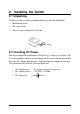
The DC power socket for the AC power adapter is located on the rear of the switch as shown below: 2.3 Installing the Switch 1. Install the switch with the AC power adapter provided. 2. Connect the power adapter cable to the switch before connecting the adapter to the AC outlet.
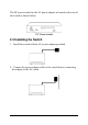
3. Making Network Connections 3.1 Network Switched Ports There are five ports on the switch for connection to five LAN segments. Each segment is an independent shared network in one collision-domain. Four 10/100BASE-TX switched ports Each port consists of one RJ-45 connector and is used for connection to either a 10BASE-T or 100BASE-TX device. The RJ-45 connectors are fixed MDI-X jacks which are designed with internal crossover function.
The following figure illustrates the front panels with different fiber connectors: 3.2 UTP Cable When making a connection to another device using straight-through UTP cable, make sure MDI-X to MDI connection rule is followed. The following figure illustrates the pin assignments of a straight-through UTP and a crossover UTP cable: It is suggested to use straight-through UTP cables for all UTP connections.
3.3 Fiber Cables For different fiber connections, several alternative models can be selected for different fiber connections as follows: Model Connector KS-115F/T ST KS-115F/C SC KS-115F/SA SC KS-115F/S3 SC KS-115F/S5 SC KS-115F/JM MT-RJ KS-115F/JS MT-RJ KS-115F/VM VF-45 KS-115F/VS VF-45 Wavelength 1300nm 1300nm 1300nm 1300nm 1300nm 1300nm 1300nm 1300nm 1300nm Cable Max.
3.
3.5 Operating Mode Four TP ports are designed as auto-negotiation capable switched ports. Each port can determine the speed and duplex type used automatically through an auto-negotiation process with the remote connected auto-negotiation device. The auto-negotiation process is performed when the connection is made. When connecting to a non-auto-negotiation device, each TP port also features the capability to auto-sense the connection speed.
4. LED Indicators 4.1 LED Panel The switch provides comprehensive LED indicators for diagnosing and monitoring the operation of the unit as illustrated below: 4.2 Interpretation PWR LED : indicates the status of the power supplied to the switch. 10/100M LED : indicates the connection speed between the TP port and the associated connected device. Link/Act. LED : indicates the link status with a connected device FDX/Col.