24-Port Gigabit Ethernet Switch KGS-2401 Installation Guide DOC.
(C) 2002 KTI Networks Inc. All rights reserved. No part of this documentation may be reproduced in any form or by any means or used to make any directive work (such as translation or transformation) without permission from KTI Networks Inc. KTI Networks Inc. reserves the right to revise this documentation and to make changes in content from time to time without obligation on the part of KTI Networks Inc. to provide notification of such revision or change.
The information contained in this document is subject to change without prior notice. Copyright (C). All Rights Reserved. TRADEMARKS Ethernet is a registered trademark of Xerox Corp. WARNING: This equipment has been tested and found to comply with the limits for a Class A digital device, pursuant to Part 15 of the FCC Rules. These limits are designed to provide reasonable protection against harmful interference when the equipment is operated in a commercial environment.
Table of Contents 1. Unpacking Information ............................................................................................. 6 2. Introduction to 24-port Gigabit Web Smart Switch ................................................ 7 2.1 General Description ............................................................................................................................... 7 2.2 Key Features ...................................................................................................
7.6 Terminology .......................................................................................................................................... 30 7.7 Command Description ......................................................................................................................... 30 7.7.1 System Commands .......................................................................................................................... 31 7.7.2 Console Commands ..................................
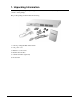
1. Unpacking Information Thank you for purchasing the 24-port Gigabit Web Smart Switch. Before you start, please check all the contents of this package. The product package should include the following: 1. One 24-port Gigabit Web Smart Switch 2. One power cord 3. Rubber foot and screws 4. Rack-mount brackets 5. One RS-232 Cable (Optional) 6.
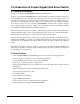
2. Introduction to 24-port Gigabit Web Smart Switch 2.1 General Description The device is a 24-port 10/100/1000Mbps Ethernet Web Smart Switch. Compare to the traditional 10/100Mbps Ethernet, the switch delivers a dedicated Gigabit connection to every attached client with no congestion issue. The gigabit ports also provide the fat pipe to the server or backbone connectivity for boosting the total system performance.
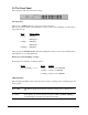
2.3 The Front Panel The front panel of the switch is shown as below: Port Operation There are 24 * 1000Mbps RJ-45 (copper) ports on the front panel.
Port LED summary table LEDs Status Interpretation 10/100M Steady /Blinking Amber Connected as 10Mbps/Active Steady/Blinking green Connected as 100Mbps/Active Steady/Blinking green Connected as 1000Mbps/Active 1000M If the port is connected but the Port LED is dark, check the following items: • The switch and the connected device power are on or not.
3. Installing 24-Port Gigabit Web Smart Switch This switch can be placed directly on your desktop, or mounted in a rack. Users can immediately use most of the features simply by attaching the cables and turning the power on. 2.1 Desktop Installation For desktop installation, the switch needs to put on a clean, flat desk or table close to a power outlet. Plug in all network cables and the power cord, then the system is ready. Before installing the switch, you must ensure: 1.
3.3 Installing Network Cables Station Connections Reference to the wiring statement of the previous section; connect each station to the switch with correct type of cables. Switch-to-Switch Connections In making a switch-to-switch connection, use every ports to connect another switch or backbone is strongly recommended. The Gigabit ports provide the fat pipe to the server or backbone connectivity for boosting the total system performance.
4. Functional Description 4.1 PHY Monitoring and Port Mode Set-up It is a major task of the software to continuously monitor the PHYs in order to set up the switch ports according to whether the link is down or up and in the latter case what the current speed, duplex mode and pause capabilities are. PHYs are being polled every 100 ms. 4.2 Flow Control In the 24-port switch flow control (back pressure) is also supported in half duplex.
5. Web Management guide This section instructs you how to enter and set up the configurations, which can be accessed by RS232 serial port (out-of-band) on the rear panel or by Internet Browser over the network (in-band). Factory Default value: IP : 192.168.1.1 Subnet Mask: 255.255.255.0 Default Gateway: 192.168.1.254 5.
3. After authentication procedure, the home page shows up. 5.2 Home Page On the Home page, you can select the configuration by clicking the menu tabs located on the upside of the UI.
To restore the default Values of switch, click the [Default] button. If you want to reboot the switch, click the [Reboot] button. To check the connection status of each port from 1 to 24, take a look at the port monitor. When the port shows green, it is connected and link up. Otherwise it is dark. To know the detail statistics of one port, click on it and the window will show.
5.2.1 System To set up the system configurations such as login value, time-out value and enabling the VLAN Management. Status & Setting Functions Mac Address The Mac Address of the switch S/W Version To check up the Software Version, see this. H/W Version The Hardware version Inactivity Timeout (Secs) Set the console inactivity timeout in seconds. The value zero disables timeout. Timeout value in seconds, 0, 60-10000.
5.2.2 Ports On the page, you can view the Port status, set up the Speed mode and enable the FDX flow control. Status & Settings Functions Link To show the status of each port. When it is red, it means the connection is down. Otherwise, it is green. Mode Choose the Speed mode of port 10/100/1000, Half/Full. To disable the port, choose Disable. If you set to auto speed, it will be auto-negotiation. FDX Flow Control To Enable the FDX Flow control, click the check box.
5.2.3 VLAN VLAN Configuration is for dividing the LAN into subnet groups for better network management. The benefit is that the user can move one client to another subnet group without actually moving the machine. VLAN Entry There are 24 entries to set up. To add new VLAN Entry, 1. Select the ports by clicking the check box. 2. Enter the VLAN ID number (1 ~ 4094) for the entry. 3. Select the member ports (PORT MEMBER) for the new VLAN entry. 4. Click [Add] to add it in the table. 5.
PVID When the VLAN-enabled switch receives a untagged packet, the packet will be sent to the port default VLAN according to the PVID (port VLAN ID) of the ingress port.
5.2.4 Aggregation/ Trunking Configuration To set up the Port trunk groups, put the ports number into the same Aggregation group line. There are eight groups to choose. The maximum number of ports for one group is 8. There three aggregation modes for selection, SMAC (Source MAC), DMAC (Destination MAC), and XOR. 5.2.5 QoS The switch provides four functions for Quality of Service. They are custom TOS, Egress Rate Control, Ingress Rate Control, and Custom Storm.
5.2.5.1 Quality of Service (QoS) TOS Configuration To improve the network performance by applying the TOS for IP packets, set up the priority of eight groups of precedence bits on this page. There are two priority levels to choose, high or Low.
5.2.5.2 QoS Port Egress Rate Control To limit the out-going packet rate, select [Enable] and enter the value you need from 250~1000000K bps. The packet rate over the limitation will be discarded. Click [Apply] to save settings. 5.2.5.3 QoS Port Ingress Rate Control To limit the in-coming packet rate, select [Enable] and enter the value you need from 250~1000000K bps.
5.2.6 Mirror Port mirror function is used to mirror traffic from source port to a target port for analysis. Only 2 ports can be monitored (mirrored) simultaneously to 1 Monitor port (target port). (Note that the target port must be in the same VLAN as the source ports.) Settings Functions Monitor Port Select the switch port, from 1 to 24 to be the target port to collect traffic info Source Ports To select the mirror ports, Click the check box of the port. Apply Click button to save settings. 5.2.
5.2.8 Discovery When you install several switches in the network, the discovery management tool helps you to search and access those switches easily. Therefore you can access any switch without memorizing the respective IP addresses. Note: The Maximum number of Address list is 16 for each mode. Auto Search 1. Click the Auto search [Apply] button to find the switches. 2. The IP address & name of Switch list will appear. 3. Click the one you want to access. Manual Add 1.
5.2.9 Default To restore all settings to factory default values, 1. Click [Default] button on the Home page 2. Click [Yes] to confirm the action. 5.2.10 Reboot To reboot the switch, 1. Click [Reboot] button on the Home page 2. Click [Yes] to confirm the action.
6. Product Specifications Standard IEEE802.3 10BASE-T IEEE802.3u 100BASE-TX IEEE802.3x full-duplex operation and flow control IEEE802.3ab 1000BASE-T IEEE802.
7. Command Line Interface 7.1 Start-up and Terminal configuration To start-up the command line interface, connect a PC COM port to the RS-232 connector and activate a terminal emulation software (e.g. HyperTerminal of Windows.). The terminal emulation software should be set up as follows: 1. Data rate: 115200 baud 2. Data format: 8 data bits, 1 stop bit and no parity 3. Flow control: none. 4.
When you are at the top level, the prompt shows :>, and if you are at the group level, the prompt displays the group name, e.g. System>. To be under a certain group, you may enter the group name at top level or add / in front of the group name then press enter at any level. Examples: At top level: >system New prompt -> System> At any level: system>/ip New prompt -> IP> To be at top level, you may enter up at any level. (ex, system>up ).
7.5 Entering Commands Commands are given by entering the command string. The command string is not case-sensitive. There are three possible situations for entering the command: 1. At any level or group: you should enter the full syntax of the command with a / in front of the syntax (ex, enter /system configuration in any level to check the system status.) 2.
7.6 Terminology The following table shows general parameter types used in command syntaxes and descriptions. The port number Comma and/or dash separated port list. This type can be used for specifying individual ports or a range of ports. The keyword none can be used to specify an empty port list. The keyword all can be used to specify all ports. Example: 1,3,812. MAC Address; format: hh-hh-hh-hh-hh-hh, hh:hh:hh:hh:hh:hh or hhhhhhhhhhhh.
7.7.1 System Commands Commands at the System level: System System System System System System Configuration [all] Restore default [keepip] UserName [] Password [] systemname [] Reboot 1. System Configuration: Syntax: System Configuration [all] Description: Show system name, software version, hardware version and management MAC address. Optionally show the full configuration [all]: Show the total switch configuration (default: System configuration only). 2.
System Reboot Description: Reboot the switch. 7.7.2 Console Commands Commands at Console level: Console Configuration Console Timeout [] Console Prompt [] 1.Console Configuration Syntax: Console Configuration Description: Show configured Console password and timeout. 2. Console Timeout Syntax: Console Timeout [] Description: Set or show the Console inactivity timeout in seconds. The value zero disables timeout. []: Timeout value in seconds, 0, 60-10000. 3.
: Port list (Default: All ports). 2. Port Mode Syntax: Port Mode [] [] Description: Set or show the speed and duplex mode for the port. : Port list (Default: All ports). : Port speed and duplex mode (Default: Show configured and current mode). 10hdx : 10 Mbit/s, half duplex. 10fdx : 10 Mbit/s, full duplex. 100hdx : 100 Mbit/s, half duplex. 100fdx : 100 Mbit/s, full duplex. 1000fdx: 1 Gbit/s, full duplex. auto : Auto negotiation of speed and duplex. 3.
Show or clear statistics for the port. : Port list (default: All ports). [clear] : Clear port statistics (default: Show statistics). 7.7.4 MAC Table Commands Commands at MAC level: MAC MAC MAC MAC MAC MAC Configuration Add |none [] Delete [] Lookup [] Flush Agetime [] 1. MAC Configuration Syntax: MAC Configuration Description: Show the permanently stored MAC table and the MAC ageing timer. 2.
5. MAC Flush Syntax: MAC Flush Description: Removes non-static MAC address from the switch MAC table. 6. MAC Age Time Syntax: MAC Agetime [] Description: Set or show the MAC age timer in seconds. The value zero disables ageing. []: Age timer in seconds, 0 or 10-65535 (default: Show timer). 7.7.
4. VLAN Lookup Syntax: VLAN Lookup Description: Lookup VLAN entry and show port list. : VLAN ID list. 5. VLAN EgressTagging Syntax: VLAN EgressTagging [] [enable|disable] Description: Set or show the VLAN Egress Tagging mode for the port. The enabled ports will strip the VLAN tag from received frames and insert the tag in transmitted frames (except PVID). The disabled ports will not strip the tag from received frames or insert the tag in transmitted frames.
Aggr Configuration Description: Shows the aggregation groups and the aggregation mode. 2. Aggregation Add Syntax: Aggr Add Description: Add link aggregation group including ports. : Aggregation port list. 3. Aggregation Delete Syntax: Aggr Delete Description: Delete link aggregation group. : Port list. Aggregations including any of the ports will be deleted. 4.
trol configuration, ingress rate control configuration and multicast storm control []: Port list (default: All ports). 2. QoS Tosprecedence Syntax: QoS Tosprecedence [] [] [low|high] Description: Set or show the IP ToS precendence priority mapping. [] : Port list (default: All ports). []: IP ToS precedence list, 0-7 (default: All precedence values). [low|high] : Internal priority (default: Show priority). 3.
7.7.8 Mirror Commands Commands at Mirror level: Mirror Configuration Mirror Port [] Mirror Source [] [enable|disable] 1. Mirror Configuration Syntax: Mirror Configuration Description: Show the mirror destination port and mirror mode for source ports. 2. Mirror Port Syntax: Mirror Port [] Description: Set or show the mirror destination port. []: Mirror destination port (default: Show mirror port). 3.
7.8 Example This example shows how to configure two VLANs with the following setup: • VID 1 spans ports 2-16 and VID 2 spans ports 1-3, so port 2 and 3 are members of both VLANs and all 16 ports must be VLAN Egress Tagging enabled. • Port 1 is the access port for VID 2, so PVID of port 1 must be set to 2.
8. Factory Default Configuration The factory default configuration is a VLAN aware L2 switch with automatic learning/ageing and auto negotiation enabled on all ports: System: The system name string is empty. Console: The password string is empty and inactivity timeout is disabled. The prompt is >. Port: All ports are enabled for auto negotiation and flow control is disabled. Max frame size is 1518. MAC table: The table is empty, auto learning and ageing is enabled. The ageing timer is 300 seconds.