KFS-0540 Industrial 5-Port Fast Ethernet Switch Installation Guide DOC.
(C) 2009 KTI Networks Inc. All rights reserved. No part of this documentation may be reproduced in any form or by any means or used to make any directive work (such as translation or transformation) without permission from KTI Networks Inc. KTI Networks Inc. reserves the right to revise this documentation and to make changes in content from time to time without obligation on the part of KTI Networks Inc. to provide notification of such revision or change.
The information contained in this document is subject to change without prior notice. Copyright (C) All Rights Reserved. TRADEMARKS Ethernet is a registered trademark of Xerox Corp. FCC NOTICE This device complies with Part 15 of the FCC Rules. Operation is subject to the following two conditions: (1) This device may not cause harmful interference, and (2) This device must accept any interference received, including the interference that may cause undesired operation.
Table of Contents 1. Introduction................................................................................................................................... 5 1.1 Features ................................................................................................................ 6 1.2 Product Panels...................................................................................................... 6 1.3 LED Indicators ..........................................................................
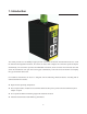
1. Introduction The switch provides five 10/100Mbps copper ports for connections to Ethernet and Fast Ethernet devices. With the featured auto-negotiation function, the switch can detect and configure the connection speed and duplex automatically. The switch also provides auto MDI/MDI-X function, which can detect the connected cable and switch the transmission wire pair and receiving pair automatically. This auto-crossover function can simplify the type of network cables used.
1.1 Features z Auto MDI/MDI-X crossover function on the copper port z Support IEEE 802.
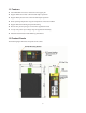
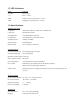
1.3 LED Indicators LED Function POWER Power status 1-5 Port 1 – Port 5 LINK Link and activity status (Port 1 - Port 5) 100M 100Mbps speed status (Port 1 - Port 5) 1.4 Specifications 10/100 Copper Ports Compliance IEEE 802.3 10Base-T, IEEE 802.3u 100Base-TX Connectors Shielded RJ-45 jacks Pin assignments Auto MDI/MDI-X detection Configuration Auto-negotiation or software control Transmission rate 10Mbps, 100Mbps Duplex support Full/Half duplex Network cable Cat.
Mounting Din-rail mounting Panel mounting (optional) Environmental Operating Temperature Typical -10oC ~ +70oC Storage Temperature -20oC ~ +85oC Relative Humidity 10% ~ 90% non-condensing Electrical Approvals FCC Part 15 rule Class B CE EMC, CISPR22 Class B EN55022:2006 EN61000-3-2:2006 EN61000-3-3:1995/A1:2001/A2:2005 Class B EN 55024:1998/A1:2001/A2:2003 IEC 61000-4-2:2001 IEC 61000-4-3:2002/A1:2002 IEC 61000-4-4:2004 IEC 61000-4-5:2001 IEC 61000-4-6:2003 IEC 61000-4-8:2001 IEC 61000-4-11:2001 S
2. Installation 2.1 Unpacking The product package contains: z The switch unit for Din-rail mounting z One product CD-ROM 2.2 Safety Cautions To reduce the risk of bodily injury, electrical shock, fire and damage to the product, observe the following precautions. z Do not service any product except as explained in your system documentation. z Opening or removing covers may expose you to electrical shock. z Only a trained service technician should service components inside these compartments.
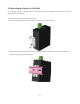
2.3 Mounting the Switch to a Din-Rail In the product package, a DIN-rail bracket is provided or has been installed for mounting the switch in a industrial DIN-rail enclosure. The steps to mount the switch onto a DIN rail are: 1. Install the mounting bracket onto the switch unit with screws as shown below: 2. Attach bracket to the lower edge of the DIN rail and push the unit upward a little bit until the bracket can clamp on the upper edge of the DIN rail.
3. Clamp the unit to the DIN rail and make sure it is mounted securely.
2.4 Mounting the Switch on a Panel The switches may be provided optionally with a panel mounting bracket. The bracket supports mounting the switch on a plane surface securely. The mounting steps are: 1. Install the mounting bracket on the switch unit.
2. Screw the bracket on the switch unit. 3.
2.5 Applying Power The switch provides two types of power interfaces, terminal block and DC power jack for receiving DC power input from external power supply. The DC power requirements no matter which interface is used for the switch are: Operating Vin Voltage Range +7V ~ +30VDC Power Consumption 2.2Watts max.
2.5.1 Using Terminal Blocks 3P Contacts Vin Positive (+) terminal Vin Negative (-) terminal Chassis ground 3P Terminal Plug A plug is provided together with the switch. The plug is shown below: Power Wires 24 ~ 12AWG (IEC 0.5~2.5mm2) Install the power source wires with the plug properly. Note: When using terminal block connectors, put a cap on the DC jack.
2.5.2 Using DC Power Jack When an external power system is not available, the switch provides a DC jack to receive power from typical AC-DC power adapter alternatively. Interfaces DC Jack ( -D 6.3mm / + D 2.0mm) Note: 1. When using DC Jack, put caps on the contacts of the terminal block. 2. Before you begin the installation, check the AC voltage of your area.
3. Making LAN Connections 3.1 10/100 Copper Ports The 10/100 RJ-45 copper ports support the following connection types and distances: Network Cables 10BASE-T: 2-pair UTP Cat. 3, 4, 5, EIA/TIA-568B 100-ohm 100BASE-TX: 2-pair UTP Cat. 5, EIA/TIA-568B 100-ohm Link distance: Up to 100 meters Auto MDI/MDI-X Function This function allows the port to auto-detect the twisted-pair signals and adapts itself to form a valid MDI to MDI-X connection with the remote connected device automatically.