Installation Guide 10/100 Fast Ethernet Adapters KF-221TX/3 DOC.
1999, KTI Networks Inc. All rights reserved. No part of this documentation may be reproduced in any form or by any means or used to make any directive work (such as translation or transformation) without permission from KTI Networks Inc. KTI Networks Inc. reserves the right to revise this documentation and to make changes in content from time to time without obligation on the part of KTI Networks Inc. to provide notification of such revision or change.
TRADEMARKS Ethernet is a registered trademark of Xerox Corp. NetWare is a registered trademark of Novell Inc. Intel, Microsoft, Toshiba are trademarks of their respective holders. This equipment has been tested and found to comply with the limits for a Class B digital device, pursuant to Part 15 of the FCC Rules.
Table of Contents 1. Introduction 1.1 Adapter Features .............................................................. 1 1.2 Connectors and LEDs ........................................................ 2 2. Wake on LAN Technology .................................................................................................. 4 3. Installing the Adapter 3.1 Installing the Adapter ......................................................... 6 3.2 Installing Wake on LAN Cable ..................................
1. Introduction The 10/100BASE-TX Fast Ethernet PCI Adapter is a 32-bit LAN adapter for use in personal computers with PCI computer bus slots. This adapter is a dual-speed adapter and features one RJ-45 connector for either a 10 Mbps IEEE 802.3 or a 100 Mbps IEEE 802.3u Ethernet network connection over unshielded twisted-pair (UTP) cable. The adapter automatically senses the connection speed, switches to either 10 Mbps or 100 Mbps and indicates the link status on the LEDs.
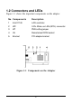
1.2 Connectors and LEDs Figure 1-1 shows the important components on the adapter. No.
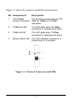
Figure 1-2 shows the connector and LEDs on the bracket. No. Components Description 1 10/100 Mbps This RJ-45 connector requires UTP network connector cable for 10Mbps or 100 Mbps connection. 2 100Mb Link LED This LED lights when 100 Mbps connection is selected and active. 3 10Mb Link LED This LED lights when 10 Mbps connection is selected and active. 4 Activity status LED This LED indicates a receive or a transmission is in process.
2. Wake on LAN Technology The adapter is an ACPI-compliant network adapter that supports the following features: _ Power management interface _ Remote wake-up (RWU) ACPI (Advanced Configuration and Power Management Interface) ACPI is a key element in Operating System Directed Power Management. It is a specification developed by Intel, Microsoft, and Toshiba Corp which allows more advanced power management features through the operating system to the hardware interfaces.
WOL Installation The adapter features : 1. One LAN controller which can support PCI power management interface and function. 2. One 3-Pin Wake on LAN (WOL) connector (JP2) 3. One PME setting jumper (JP1) 4. One Wake on LAN (WOL) cable The 3-pin WOL connector (JP2) provides an interface to the system motherboard for auxiliary power and Power Management Enable signal through the WOL cable. The PME setting jumper (JP1) specifies the active level of the PME signal coming from the system motherboard.
3. Installing the Adapter This chapter describes how to install the Fast Ethernet PCI adapter in a PCI computer and how to connect the adapter to the network. Before installing the adapter, you need the following: A computer system that is compliant with the PCI specifications version 2.0 or later.
5. Insert the adapter into the slot and secure the screw (see Figure 3-1). 6. Install the WOL cable, if necessary. Refer to 3.2 for the details. 7. Replace the computer cover and reconnect all previously connected cables. Figure 3-1 Inserting the Adapter into the PCI Slot 3.2 Installing Wake on LAN Cable Follow the steps to install the Wake on LAN cable: 1. Make sure your system motherboard is RWU capable. 2. Make sure WOL function is enabled in the system BIOS. 3.
Figure 3-2 PME Jumper JP1 Setting 4. Locate the 3-Pin WOL connector on the system motherboard. 5. Plug one end of the WOL cable to the 3-Pin WOL connector of the adapter. 6. Plug the other end of the WOL cable to the 3-Pin WOL connector on the system motherboard.
3.3 Connecting to the Network The rear bracket of the Fast Ethernet adapter contains one RJ-45 connector. The connector is used for either 100Mbps 100BASETX connection or 10Mbps 10BASE-T connection. The adapter can sense the connection speed and switch to appropriate operation automatically.
10 Mbps Connection For 10BASE-T Ethernet networks, the Fast Ethernet adapter uses Category 3, 4, or 5 UTP cable. To establish a valid 10 Mbps connection, the cable must be connected to a 10BASE-T hub. Connect the network cable as follows: 1. Make sure that the plug on the cable is wired appropriately for a standard 10BASE-T adapter. 2. Align the RJ-45 plug on the end of the UTP cable with the notch on the adapter's connector and insert it into the adapter connector as shown in Figure 3-4.
100 Mbps Connection For 100BASE-TX Fast Ethernet networks, the adapter supports Category 5 UTP cabling. To establish a valid 100 Mbps connection, the cable must be connected to a 100BASE-TX hub. 1. Make sure that the plug on the cable is wired appropriately for a standard 100BASE-TX adapter. 2. Align the RJ-45 plug on the end of the UTP cable with the notch on the adapter's connector and insert it into the adapter connector as shown in Figure 3-5.
4. Network Driver Installation After making the connection to the network, you must install the adapter network driver in order to connect the Fast Ethernet adapter to your network operating system. 4.1 Driver Information The adapter driver media contains the latest versions of the network drivers available when the adapter is shipped from the factory. A file, \README.
In addition to the basic drivers, more updated information and drivers may be included in the driver media after this guide is published. Please refer to the \README.DOC file first for the latest information before you install any drivers. 4.2 BIOS Setup Before installing the driver, it is recommended to run the system BIOS setup utility to check each PCI slot that contains a Fast Ethernet PCI adapter for the following PCI settings: 1.
4.3 Installation for Windows 98 System After the driver installation for Windows 98, there are some simple methods to check the installation is proper or not as follows: 1.
The adapter name shown in Device Manager should be "KF221TX Fast Ethernet PCI Adapter". The installation is proper if there is no "?" or "!" mark ahead of the adapter line. 2. If you are using TCP/IP protocol, you can use Ping command under DOS mode to check the adapter itself. The command is >ping 127.0.0.
5. LED Indicators Each Fast Ethernet adapter has three LEDs, as shown in Figure 1-2. 5.1 Interpretations The interpretations of the LEDs are: 100Mb LED indicates an active 100Mbps connection is established. On : Good connection between adapter and 100BASE-TX device Off : No active connection Blink: Not applicable 10Mb LED indicates an active 10 Mbps connection is established.
Appendix A1. Specifications Network std.: 10 MbpsIEEE 802.3 10BASE-T Ethernet 100 Mbps IEEE 802.3u 100BASE-TX Fast Ethernet Speed : Auto-sense, auto-negotiation, 10Mbps, 100Mbps Duplex : Auto-negotiation, Half-duplex and full-duplex Bus Interface: PCI 2.0 or later Network Cable: 10Mbps Category 3, 4, or 5 UTP (100 meters) 100Mbps Category 5 UTP (100 meters) Wake on LAN: 3-Pin Wake on LAN connector One Wake on LAN cable Boot ROM: 128KB boot ROM socket Dimensions: 59mmx130mm (2.32"x5.
A.2 Auto-negotiation Function The adapter is equipped with an auto-negotiation function. Autonegotiation is a negotiation procedure between two connected devices. Both devices must be auto-negotiation capable. The procedure decides the best operation modes that can be used for the data transfer operation between two connected devices.
A.3 Installing Remote Boot ROM Before you can use the remote boot function, you have to setup the remote boot service on the file server and install the remote boot ROM onto the adapter. To install the boot ROM, make sure the notch of the boot ROM is in the same direction as the notch of the socket on the adapter. The remote boot ROM socket is labeled U5 on the adapter.