INDUSTRIAL 10/100BASE-TX TO 100BASE-FX MEDIA CONVERTERS KCD-300 Series Installation Guide DOC.
(C) 2006 KTI Networks Inc. All rights reserved. No part of this documentation may be reproduced in any form or by any means or used to make any directive work (such as translation or transformation) without permission from KTI Networks Inc. KTI Networks Inc. reserves the right to revise this documentation and to make changes in content from time to time without obligation on the part of KTI Networks Inc. to provide notification of such revision or change.
The information contained in this document is subject to change without prior notice. Copyright (C) All Rights Reserved. TRADEMARKS Ethernet is a registered trademark of Xerox Corp. FCC NOTICE This device complies with Class B Part 15 the FCC Rules. Operation is subject to the following two conditions: (1) This device may not cause harmful interference, and (2) this device must accept any interference received including the interference that may cause.
Table of Contents 1. Introduction ......................................................... 5 1.1 1.2 1.3 1.4 Features ........................................................................................ 6 Specifications ................................................................................ 7 Model Specifications ................................................................... 12 Special Functions ........................................................................ 13 2.
1. Introduction The industrial 10/100BASE-TX to 100BASE-FX media converter series provides industrial strength Ethernet copper-to-fiber media conversion, allowing for 10Base-T-100Base-FX or 100Base-TX-100Base-FX over multimode or optional single-mode fiber optical media.
1.1 Features • • • • • • • • • • • • • • • • • Convert speed and media type Support full wire speed conversion Support 10Mbps and 100Mbps speed on TP (copper) connections Auto MDI/MDI-X detection function on the TP (copper) port Auto-negotiation function on the TP port Link fault pass through function Provide comprehensive manual configuration settings Transparent conversion to 802.
1.
Twisted-Pair Interface (TP Port, Copper Port) Connector Shielded RJ-45 Pin Assignments Auto MDI/MDI-X detection Signal Compliance IEEE 802.3 10Base-T, 802.3u 100Base-TX Data Speed 10Mbps or 100Mbps Duplex Mode Half-duplex or Full-duplex Configuration Auto-negotiation capable and optional forced manual settings Cable Types 10Mbps - Cat. 3, 4, or 5 UTP 100Mbps - Cat. 5 UTP Supported Link Distance Up to 100 meters Fiber Optic Interface (FX Port) Signal Compliance IEEE 802.
Configuration Setting Switches (SW) NO. FUNCTION SETTINGS SW1 TP Port mode OFF Auto-negotiation (default) ON Forced mode SW2 TP Port Duplex OFF Full duplex (default) ON Half duplex SW3 TP Port Speed OFF 100Mbps (default) ON 10Mbps SW4 Link Fault Pass Through OFF Enable (default) ON Disable SW5 Forwarding mode OFF Store-and-forward alwayes (default) ON Smart-forward mode SW6 802.
DC Power Input Interface Operating Input Voltages Power consumption Basic Information Forwarding Throughput Packet Types Packet Length Flow Control Screw-type terminal block ( 2 sets for power wire cascading) DC Jack (-D6.3mm/+D2.0mm) +7V ~ +30V(+5%) 1.7W @+7.5VDC input 2.4W @+24VDC input 2.6W @+30VDC input Full wire speed at 100M full duplex 10Mbps - 14,880 pps at 64-byte packets 100Mbps - 148,800pps at 64-byte packets Transparent and no modification for - IEEE 802.3 standard packets - IEEE 802.
Certificate FCC CE/EMC CE/LVD Safety Part 15 Class B EMI EN50081-1 Class B EMS EN55024 EN 60950 EN 50081-1/1992 : EN55022:1994/A1:1995/A2:1997 EN61000-3-2:2000 EN61000-3-3:1995/A1:2001 CISPR Class B Device <75W Clause 5 EN 55024:1998/A1:2001 IEC 61000-4-2:1995 ESD Test IEC 61000-4-3:1995 RS Test IEC 61000-4-4:1995 EFT/BURST Test IEC 61000-4-5:1995 Surge Test IEC 61000-4-6:1996 CS Test IEC 61000-4-8:1993 Magnetic Field IEC 61000-4-11:1994 Volatge Int.
1.3 Model Specifications The media converter series provides the following fiber options: Model Specifications Model FX Con. Wavelength Fiber Distance Op.
1.4 Special Functions Auto MDI/MDI-X Function This function allows the TP port to auto-detect the twisted-pair signals and adapts itself to form a valid MDI to MDI-X connection with the remote connected device automatically. Auto-negotiation Function When TP port is set on Auto-negotiation mode (SW1:ON), it is featured with auto-negotiation function and full capability.
Link Fault Pass Through Function When this function is enabled, a link fault detected on the TP port will force a link down on the FX port. Similarly, a link fault detected on the FX port will also force a link down on the TP port. As illustrated in the following figure, this function allows to pass TP link fault to the remote link partner and makes the converter like a TP cable extender. Smart-Forward Mode Refer to Section 3.1.1 for the description of Smart-Forward.
2. Installation 2.1 Unpacking Check that the following components have been included: • Information CD • The Media Converter unit • DIN-rail mounting bracket If any item is found missing or damaged, please contact your local reseller for replacement. The following are available optional accessories: • Panel Mounting Bracket • The bracket is used for mounting the converter on a panel surface. Commercial-rated AC power adapters: Rated AC120V/60Hz DC7.5V 1A Rated AC230V/50Hz DC7.
2.2 DIN-Rail Mounting In the product package, a DIN-rail bracket is provided for mounting the converter in a industrial DIN-rail enclosure. The steps to mount the converter onto a DIN-rail are: 1. Clamp the bracket into the rear of the converter. Align the bracket with the rear face of the converter and screw it onto the converter unit. 2. Unscrew and loose the mounting clamp plate of the bracket. Mount the bracket with the converter onto the DIN rail.
5. Screw the clamp with the bracket and make sure the converter is properly fixed on the DIN rail.
Make sure that there are proper heat dissipation from and adequate ventilation around the device.
2.3 Mounting on a Panel Surface An optional mounting bracket, as shown below is also available for mounting the converter on a panel surface such as a wall, a wood board, or a metal plate in an industrial enclosure. To mount the converter on a panel surface, the steps are: 1.
2. Mount and screw the converter on the target surface. The final dimension after bracket installation is also shown below: Make sure that there are proper heat dissipation from and adequate ventilation around the device. Do not place heavy objects on the device.
2.4 Applying Power The converter provide two types of power interfaces, terminal block and DC power jack for receiving DC power input from external power supply. DC Power Input Specification Operating Voltage +7 ~ +30VDC Power Consumption Max. 2.6W @30VDC DC Power Terminal Block Connectors Screw-type Terminal block (2 sets) Pin Assignments DC1 + - Positive (+) Negative (-) terminals DC2 + - 2nd Positive (+) Negative (-) terminals Power wires 24 ~ 12AWG (IEC 0.5~2.
DC2 + and DC2 - can be installed with another power-pair for delivering the main power input to next converter in a cascading way. Note: Only up to four converter units can be cascaded to receive power from one main power input source. DC Power Jack Connector: Jack D 6.3mm D 2.0mm AC Power Adapters: Optional commercial rated adapters are available for purchasing. Rated AC120V/60Hz DC7.5V 1A Rated AC230V/50Hz DC7.5V 1A Rated AC100V/50-60Hz DC7.5V 1A Rated AC240V/50Hz DC7.
2.5 Making TP Port Connection TP port is featured to support connection to : • Auto-negotiation devices • Auto-negotiation incapable 10BASE-T devices • Auto-negotiation incapable 100BASE-TX devices Network Cables 10BASE-T: 2-pair UTP Cat. 3,4,5 , EIA/TIA-568B 100-ohm STP 100BASE-TX: 2-pair UTP Cat. 5, EIA/TIA-568B 100-ohm STP Link distance: Up to 100 meters Note: The TP port is featured with auto MDI/MDI-X crossover detection and configuration function.
2.6 Making FX Port Connection FX port operates on 100Mbps and full duplex (factory default). A variety of fiber options is provided as listed in Section 1.3. Network Cables Multimode (MMF) - 50/125, 62.
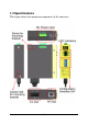
3 Configuration Switches & LED Indicators The following figure shows the locations of the configuration switches and LED indicators: Refer to the following sections for the related functions.
3.1 Configuration Switches SW FUNCTION SW1 TP Port mode SETTING&STATE OFF Auto-negotiation (default) ON Forced mode SW2 TP Port Duplex OFF ON Full duplex (default) Half duplex SW3 TP Port Speed OFF ON 100Mbps (default) 10Mbps SW4 Link Fault Pass Through OFF ON Enable (default) Disable SW5 Forwarding mode OFF ON Store-and-forward always (default) Smart-forward mode SW6 802.
3.1.1 Forwarding Mode Setting SW5 The following table lists the forward method used in different TP to FX conversions: SW5 Setting TP port to/from FX port Store-and-forward 10BASE-T to 100BASE-FX 100BASE-TX to 100BASE-FX Smart-forward 10BASE-T to 100BASE-FX 100BASE-TX to 100BASE-FX Forward method Store and forward Store and forward Store and forward Direct conversion On smart-forward mode, the converter can change to direct conversion automatically when it detects same speed on both TP port and FX port.
3.1.3 FX Duplex Setting SW7 This setting is used to set the duplex mode of the FX port. It is recommended to use full duplex mode for FX connection unless its link partner is a fixed half duplex device. Half duplex mode will shorten the connection distance.
3.