
Installation guide


-9-
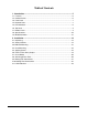
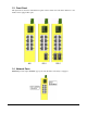
1.6 Top Panel
All three model series provide same top panel as figure shown below:
The main functions are:
DC Power Jack This connector is used when a AC-DC power adapter is used as a power
source to the switch.
Terminal Block This connector provides the following interfaces:
DC1 Positive(+) and Negative(-) - VDC power input from power system
DC2 Positive(+) and Negative(-) - VDC power cascaded to next device
PF Positive(+) and Negative(-) - Power failure relay output
Reset Hardware reset push button
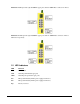
1.7 Bottom Panel
All three model series provide same bottom panel as figure shown below:
The switch block SW is used for selecting the media connector type for Port 7 and Port 8.
Model SW ON Position OFF Position
800 SW1 - Reserved
SW2 - Reserved
800-1 SW1 - Reserved
SW2 Select FX8 Select 10/100TX RJ-45 TP8
800-2 SW1 Select FX7 Select 10/100TX RJ-45 TP7
SW2 Select FX8 Select 10/100TX RJ-45 TP8