KSD-800 Series Industrial 8-Port Fast Ethernet Switches with Fiber Connectivity Installation Guide DOC.
(C) 2002 KTI Networks Inc. All rights reserved. No part of this documentation may be reproduced in any form or by any means or used to make any directive work (such as translation or transformation) without permission from KTI Networks Inc. KTI Networks Inc. reserves the right to revise this documentation and to make changes in content from time to time without obligation on the part of KTI Networks Inc. to provide notification of such revision or change.
The information contained in this document is subject to change without prior notice. Copyright (C). All Rights Reserved. TRADEMARKS Ethernet is a registered trademark of Xerox Corp. WARNING: This equipment has been tested and found to comply with the limits for a Class A digital device, pursuant to Part 15 of the FCC Rules. These limits are designed to provide reasonable protection against harmful interference when the equipment is operated in a commercial environment.
Table of Contents 1. Introduction .................................................................................................. 5 1.1 1.2 1.3 1.4 1.5 1.6 1.7 1.8 1.9 Features ................................................................................................................... 6 Product Panels ......................................................................................................... 6 Front Panel ..............................................................................
1. Introduction The KSD-800 series is 8-port full wire speed Fast Ethernet switches for industrial applications. Depending on the fiber connectivity, the series is provided in three types of configuration as follows: Model series 800 800-1xxx 800-2xxx 10/100TX TP Ports 8 ports 8 ports 8 ports 100FX fiber ports 1 port 2 ports The switches provide the following advantages: Plug and Play The switches provide eight 10/100TX copper ports for connections to Ethernet devices or 100Mbps Fast Ethernet devices.
1.1 Features • Fast Ethernet switch with 8 10/100TX copper ports • Auto MDI/MDI-X detection on all 10/100TX ports • Auto-negotiation capable on all 10/100TX ports • 100FX slots support wide range of fiber options - ST, SC connectors - Multi-mode fiber, Single mode duplex fiber • Far End Fault function on 100FX ports • Back pressure flow control for half duplex operation • IEEE 802.
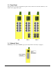
1.3 Front Panel The figure below shows the individual front panel of three model series. The main difference is the number of the equipped fiber ports. 1.4 Network Ports Model 800 provides eight 10/100TX copper ports only. No fiber connectivity is equipped.
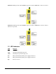
Model 800-1 series provide eight 10/100TX copper ports and one 100FX fiber connector on Port 8. Model 800-2 series provide eight 10/100TX copper ports and one 100FX fiber connector on Port 7 and Port 8 respectively. 1.5 LED Indicators LED Function PWR Power status LNK Network port link status (per port) 100M Network port speed status (per port) FX7 Fiber port link status (if fiber port is equipped on Port 7) FX8 Fiber port link status (if fiber port is equipped on Port 8) Mgt.
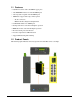
1.6 Top Panel All three model series provide same top panel as figure shown below: The main functions are: DC Power Jack This connector is used when a AC-DC power adapter is used as a power source to the switch.
1.8 Specifications Network Ports Switched Port Number Port 1 Port 2 Port 3 Port 4 Port 5 Port 6 Port 7 Port 8 Model 800 10/100TX 10/100TX 10/100TX 10/100TX 10/100TX 10/100TX 10/100TX 800-1 series 10/100TX 10/100TX 10/100TX 10/100TX 10/100TX 10/100TX 10/100TX 10/100TX 10/100TX 100FX 800-2 series 10/100TX 10/100TX 10/100TX 10/100TX 10/100TX 10/100TX 10/100TX 100FX 10/100TX 100FX Note: 10/100TX - TP RJ-45, 100FX - Fiber 10/100TX Twisted Pair Ports (TP) Compliance IEEE 802.3 10BASE-T, IEEE 802.
Switch Functions MAC Addresses Table 1K entries Forwarding & filtering Non-blocking, full wire speed 10Mbps - 14,880 pps at 64-byte packets 100Mbps - 148,800pps at 64-byte packets Switching technology Store and forward Maximum packet length 1536 bytes Broadcast storm 64 consecutive broadcast packets in 800ms Protection by dropping broadcast storm packets LED Indicators System Power status Per 10/100TX port TP port link/activity status, speed status Per 100FX port FX port link status DC Power I
1.
A variety of fiber options and the optical specifications is provided as follows: Model FX Port & Cable Wavelength Tx Power Rx sensitivity Rx max. power 800-1T FX8 : ST MMF 1310nm -19 ~ -14 dBm -34 dBm max. -14 dBm min. 800-1C FX8 : SC MMF 1310nm -19 ~ -14 dBm -34 dBm max. -14 dBm min. 800-1CL1 FX8 : SC MMF 1310nm -19 ~ -12 dBm -31 dBm max. -8 dBm min. 800-1CL2 FX8 : SC MMF 1310nm -19 ~ -14 dBm -34 dBm max. -3 dBm min. 800-1SA2 FX8 : SC SMF 1310nm -15 ~ -8 dBm -34 dBm max.
2. Installation 2.1 Unpacking The product package contains: • The switch unit • One DIN-rail mounting kit • One product CD-ROM 2.2 Safety Cautions To reduce the risk of bodily injury, electrical shock, fire, and damage to the equipment, observe the following precautions. • Do not service any product except as explained in your system documentation. • Opening or removing covers may expose you to electrical shock. • Only a trained service technician should service components inside these compartments.
2.3 DIN-Rail Mounting In the product package, a DIN-rail bracket is provided for mounting the switch in a industrial DIN-rail enclosure. The steps to mount the switch onto a DIN rail are: 1. Install the mounting bracket onto the switch unit as shown below: 2. Attach bracket to the lower edge of the DIN rail and push the unit upward a little bit until the bracket can clamp on the upper edge of the DIN rail. 3. Clamp the unit to the DIN rail and make sure it is mounted securely.
2.4 Panel Mounting The switches are provided with an optional panel mounting bracket. The bracket support mounting the switch on a plane surface securely. The mounting steps are: 1. Install the mounting bracket on the switch unit. 2. Screw the bracket on the switch unit.
3. Screw the switch unit on a panel.
2.5 Applying Power The power specifications of the switch are: Operating Voltage Power Consumption +7 ~ +30VDC Max. 7.3W @30VDC The switch provides two types of power interfaces, terminal block and DC power jack for receiving DC power input from external power supply. Using Terminal Blocks Either DC1 interface or DC2 interface can be used to receive DC power from an external power system. Or, DC2 also can be used to deliver the power received on DC1 to next switch in cascading way.
Using DC Power Jack When an external power system is not available, the switch provides a DC jack to receive power from typical AC-DC power adapter alternatively. AC Power Adapters: Optional commercial rated adapters are available for purchasing. Rated AC120V/60Hz DC7.5V 1A Rated AC230V/50Hz DC7.5V 1A Rated AC100V/50-60Hz DC7.5V 1A Rated AC240V/50Hz DC7.5V 1A Note: Before you begin the installation, check the AC voltage of your area.
2.7 Reset Button The reset button is used to perform a hardware reset to the switch. It is not used in normal cases and can be used for diagnostic purpose. If any network hanging problem is suspected, it is useful to push the button to reset the switch without turning off the power. Check whether the network is recovered. 2.8 Selecting UTP or Fiber If the switch is equipped with FX7 port or FX8 port, it is required to select the media type to be used for the switched Port 7 and Port 8.
2.9 Making UTP Connections The 10/100TX ports supports the following connection types and distances: Network Cables 10BASE-T: 2-pair UTP Cat. 3,4,5 , EIA/TIA-568B 100-ohm 100BASE-TX: 2-pair UTP Cat. 5, EIA/TIA-568B 100-ohm Link distance: Up to 100 meters The ports are equipped with auto MDI/MDI-X function and auto-negotiation function for the UTP connection.
2.10 Making Fiber Connections FX7 port and FX8 port operate on 100Mbps and full duplex. The following figure illustrates a connection example between two fiber ports: Make sure the Rx-to-Tx connection rule is followed on the both ends of the fiber cable. Far End Fault Function The FX ports are facilitated with this function, which conforms to IEEE 802.3u 100BASE-FX specifications.
2.11 LED Indication LED Function State Interpretation PWR Power status ON OFF The power is supplied to the switch. The power is not supplied to the switch. LNK Port link status ON An active link is established on the port. (No traffic) BLINK Port link is up and there is traffic. OFF Port link is down. 100M Port speed status ON OFF FX7 FX7 link status ON FX7 port is link up. BLINK Port link is up and there is traffic. OFF Port link is down. FX8 FX8 link status ON FX8 port is link up.